Restoration and conservative rehabilitation of the “Torri Eur” real estate complex.
Category: Civil buildings
Services: Final design
Period: April 2021 – ongoing
Client: MBM S.p.A.

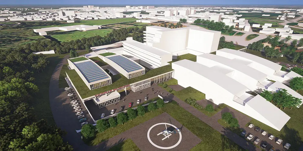
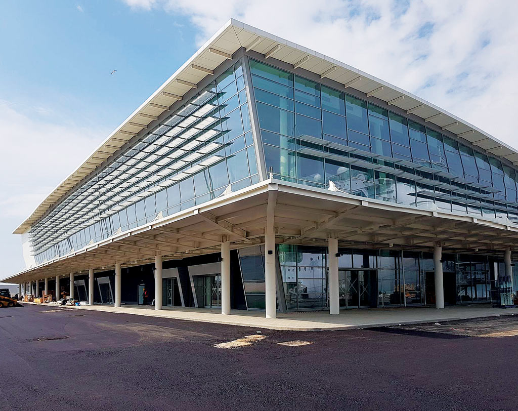
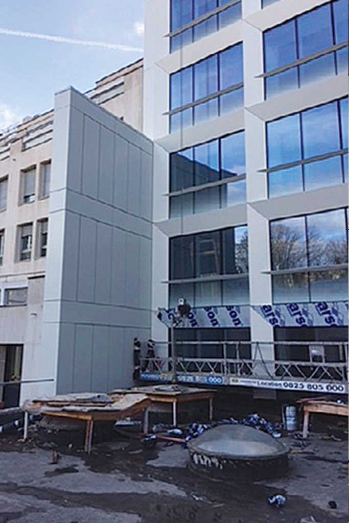
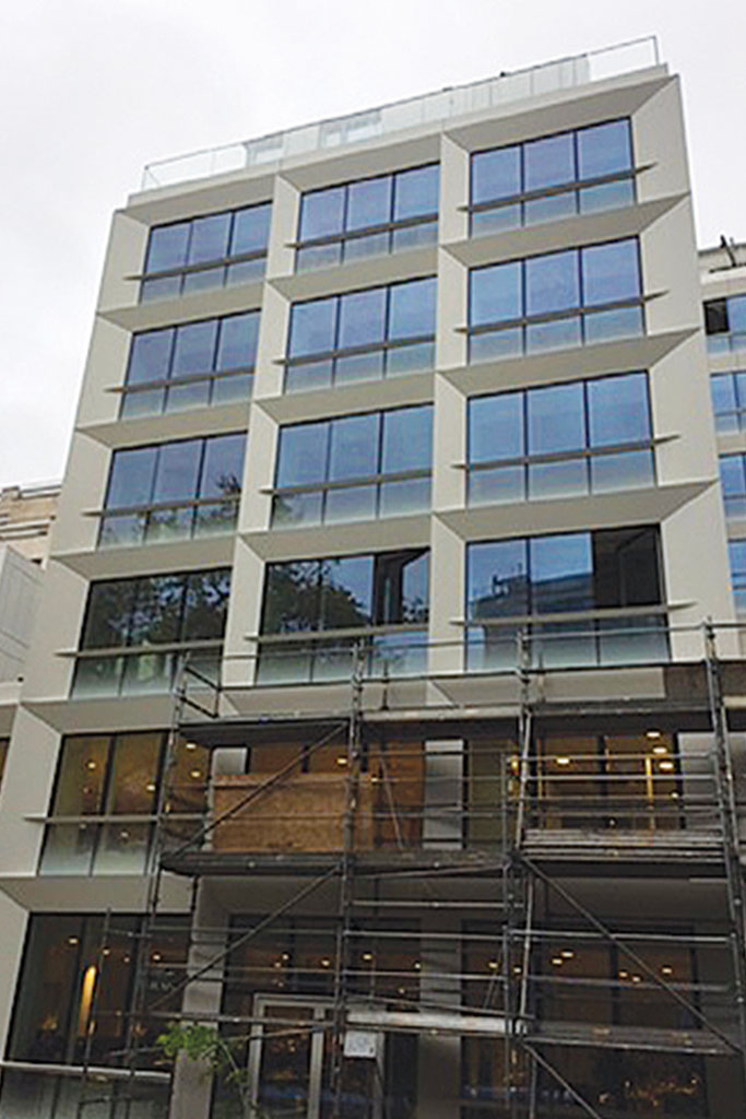
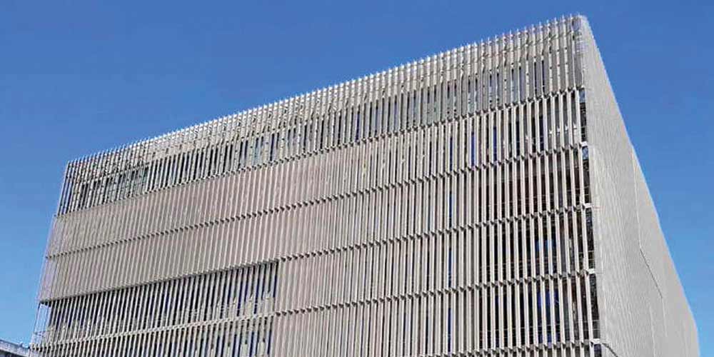
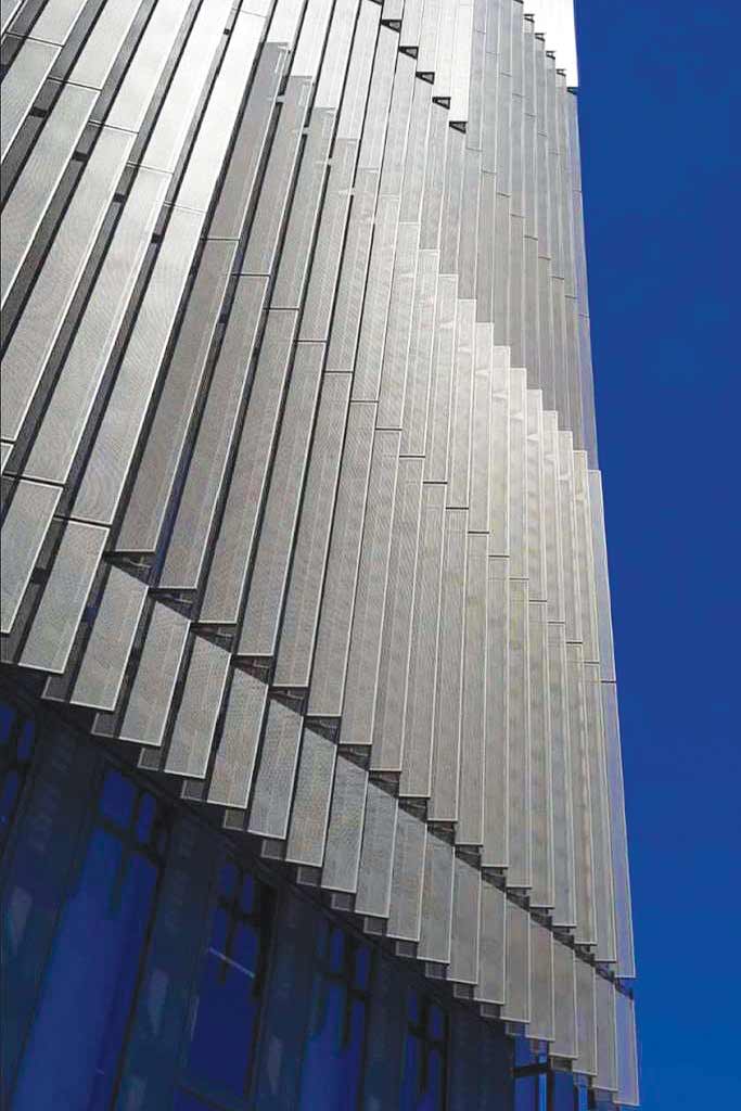
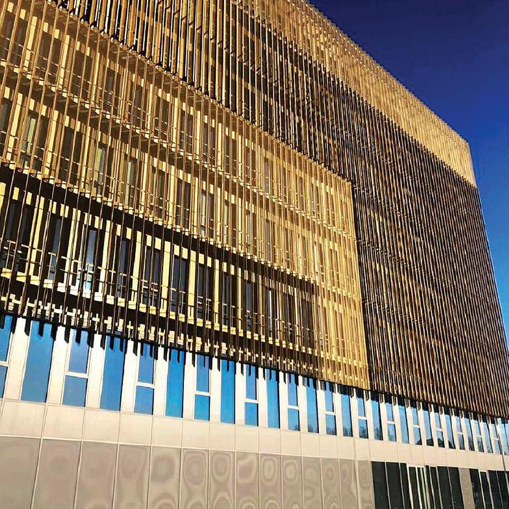
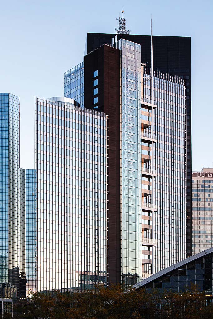
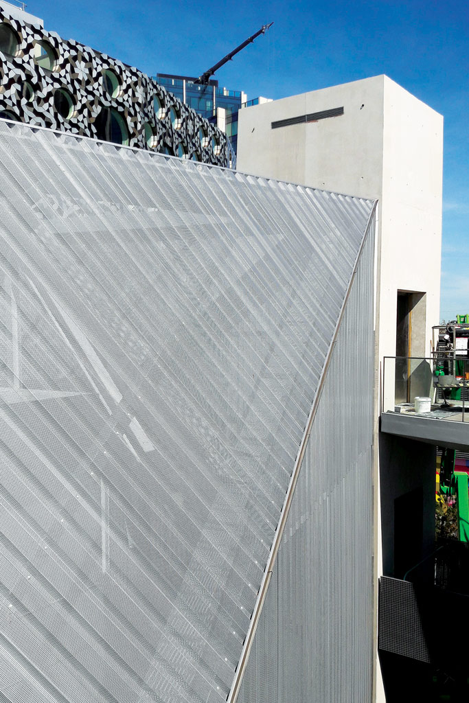
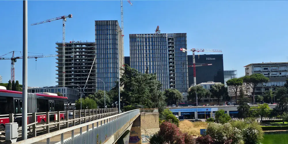
The EUR towers complex is made up of a group of several buildings which, having considerable architectural and urban planning importance, were once redeveloped and transformed into Telecom’s headquarters.
The intervention lot, located in the municipality of Rome, on the northern side of the EUR artificial lake and close to the EUR Fermi metro station, has dimensions in plan of approximately 154 m x 100 m, and a surface area of over 15,500 m2.
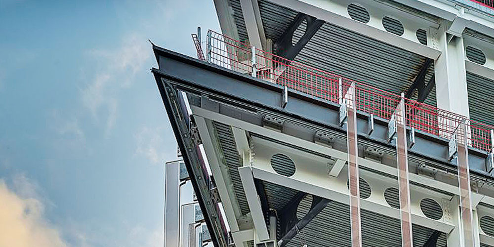
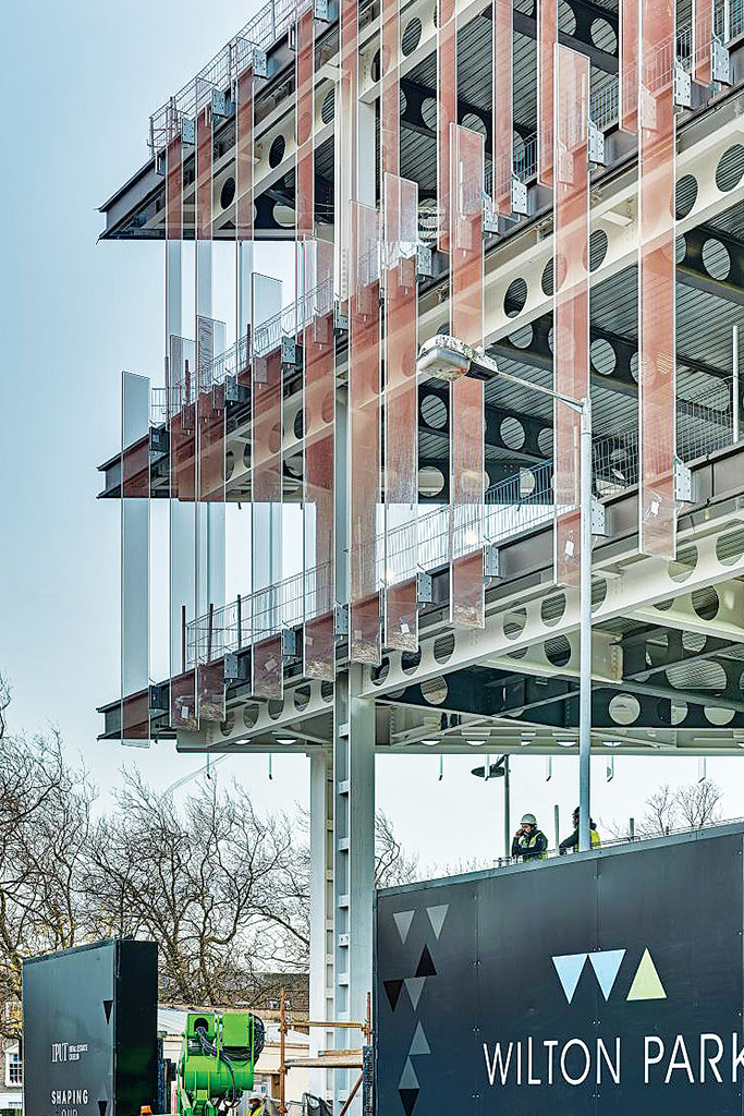
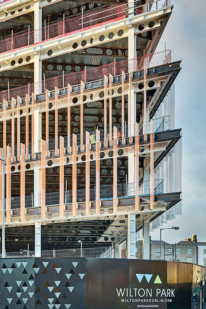
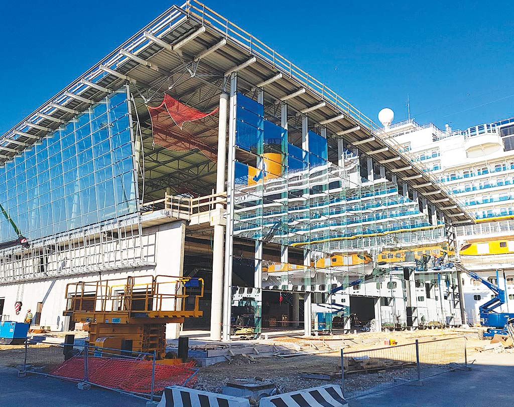
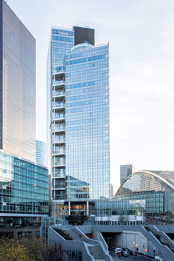
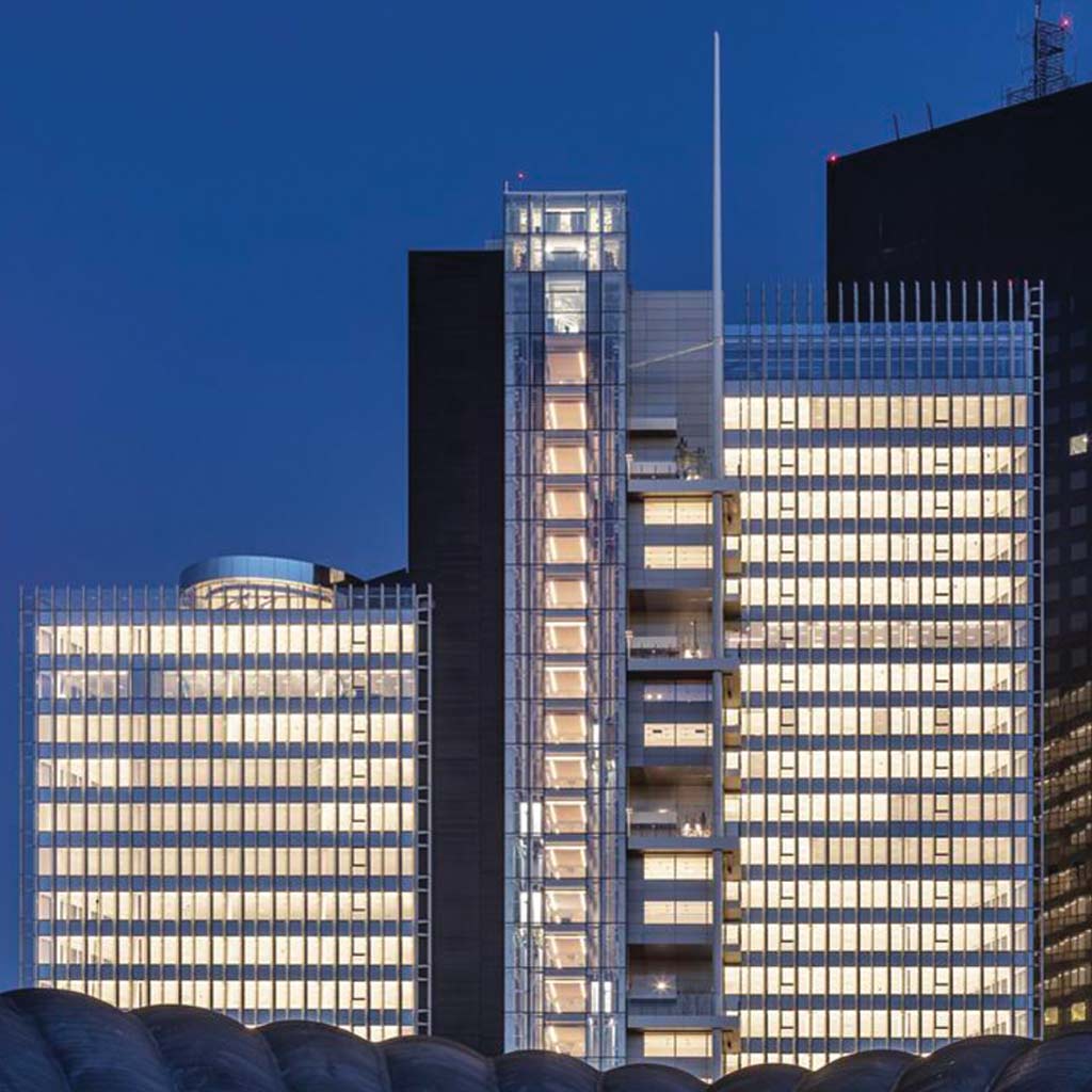
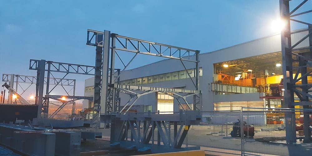
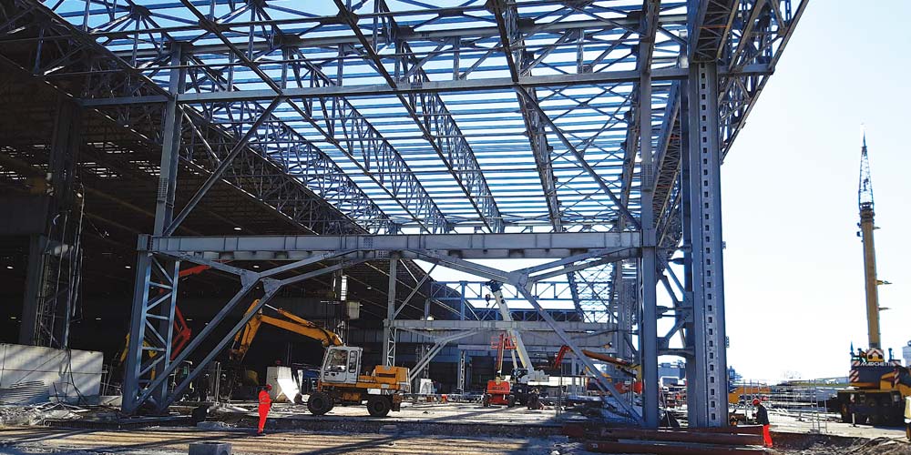
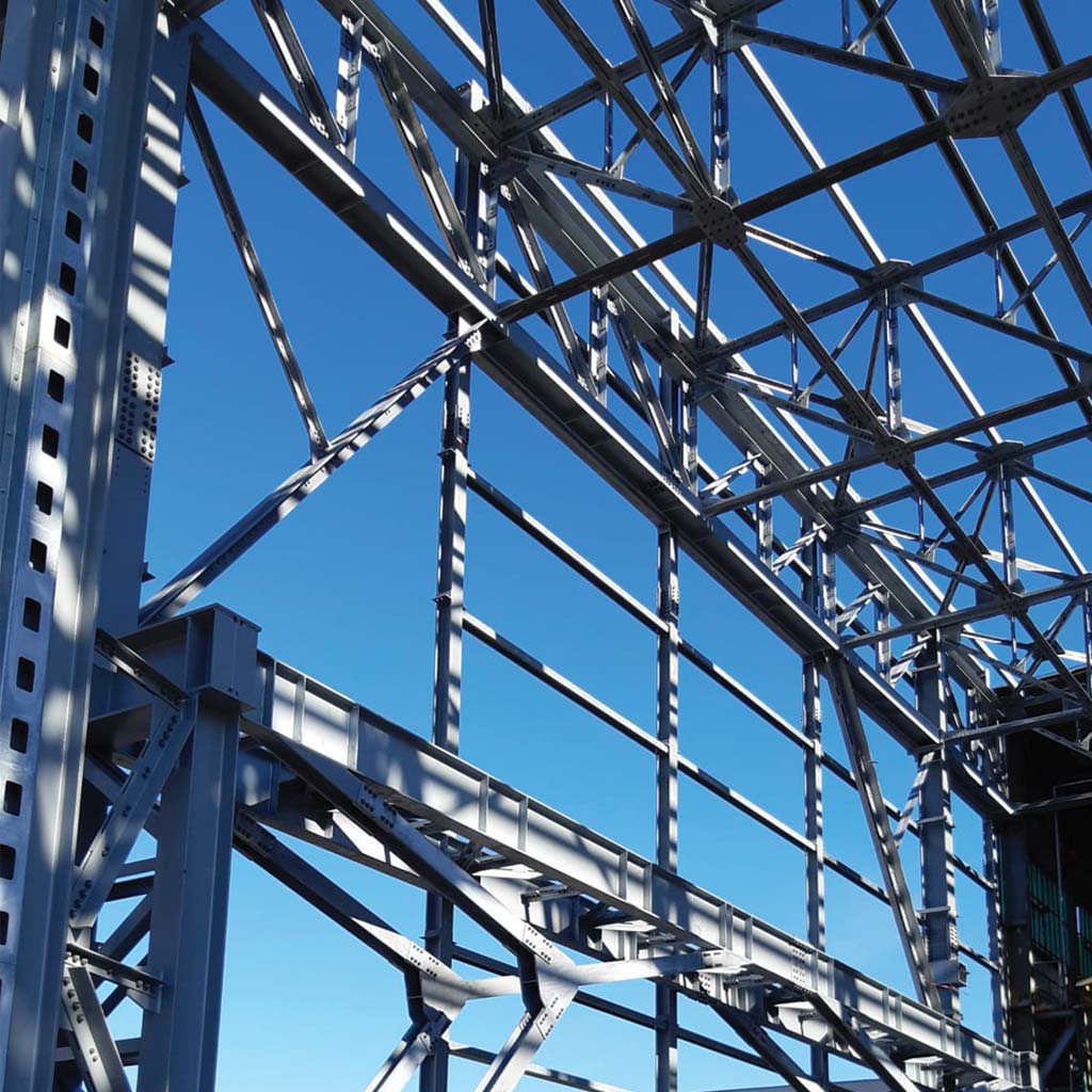
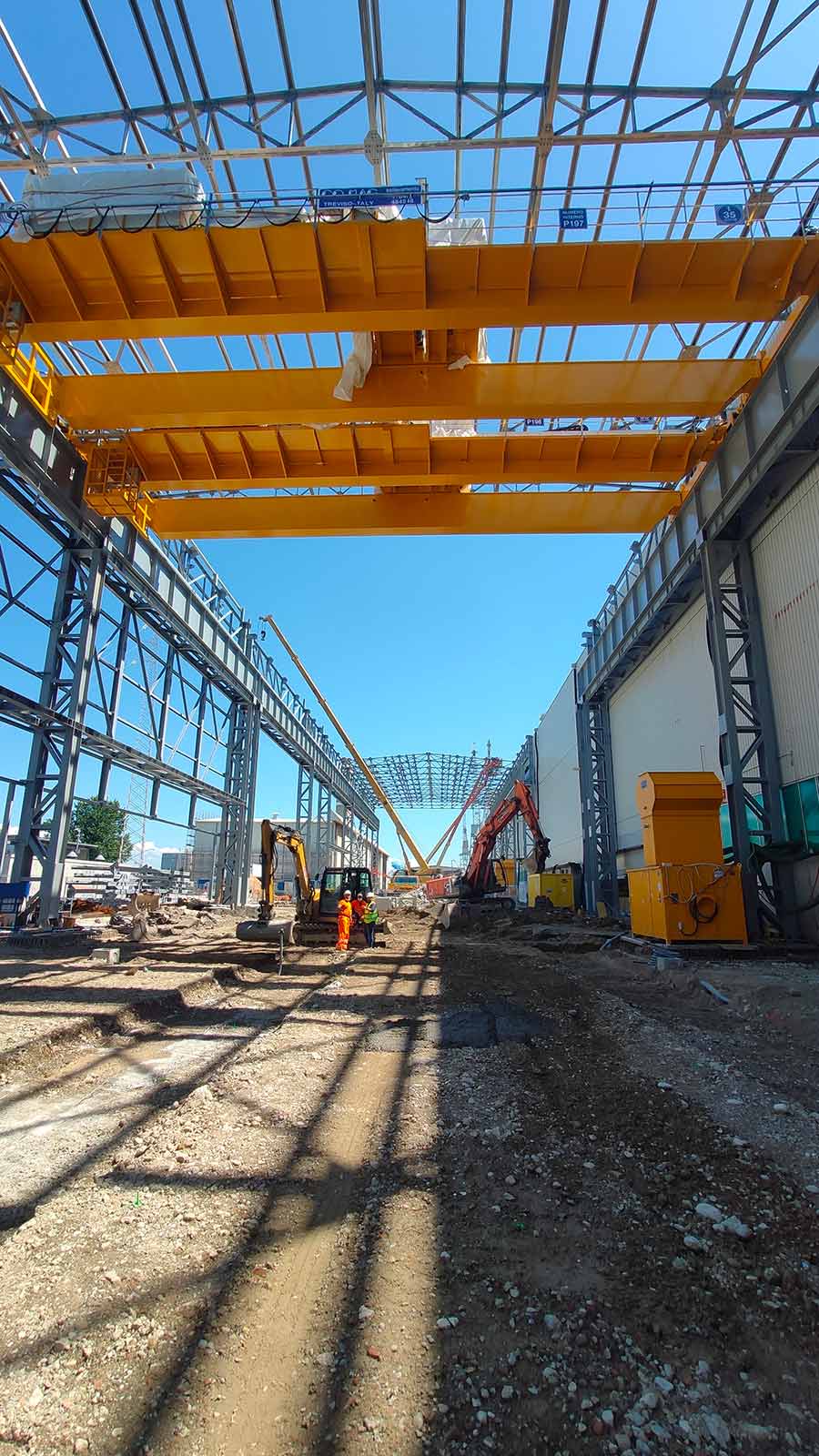
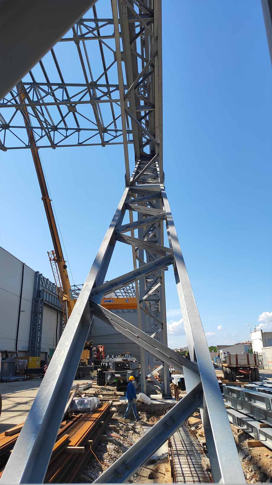
The structural project handled by Steel Project Engineering is part of a larger restoration and conservative rehabilitation intervention, in order to achieve seismic and static adaptation to current regulations, while remaining faithful to the original project with interventions targeted on critical structural elements. Our studio, specifically, dealt with the executive and construction project for all aspects concerning the metal structures (for a total of approximately 6,000 tons) and the interfaces with the existing reinforced concrete structures.

The structural project handled by Steel Project Engineering is part of a larger restoration and conservative rehabilitation intervention, in order to achieve seismic and static adaptation to current regulations, while remaining faithful to the original project with interventions targeted on critical structural elements. Our studio, specifically, dealt with the executive and construction project for all aspects concerning the metal structures (for a total of approximately 6,000 tons) and the interfaces with the existing reinforced concrete structures.
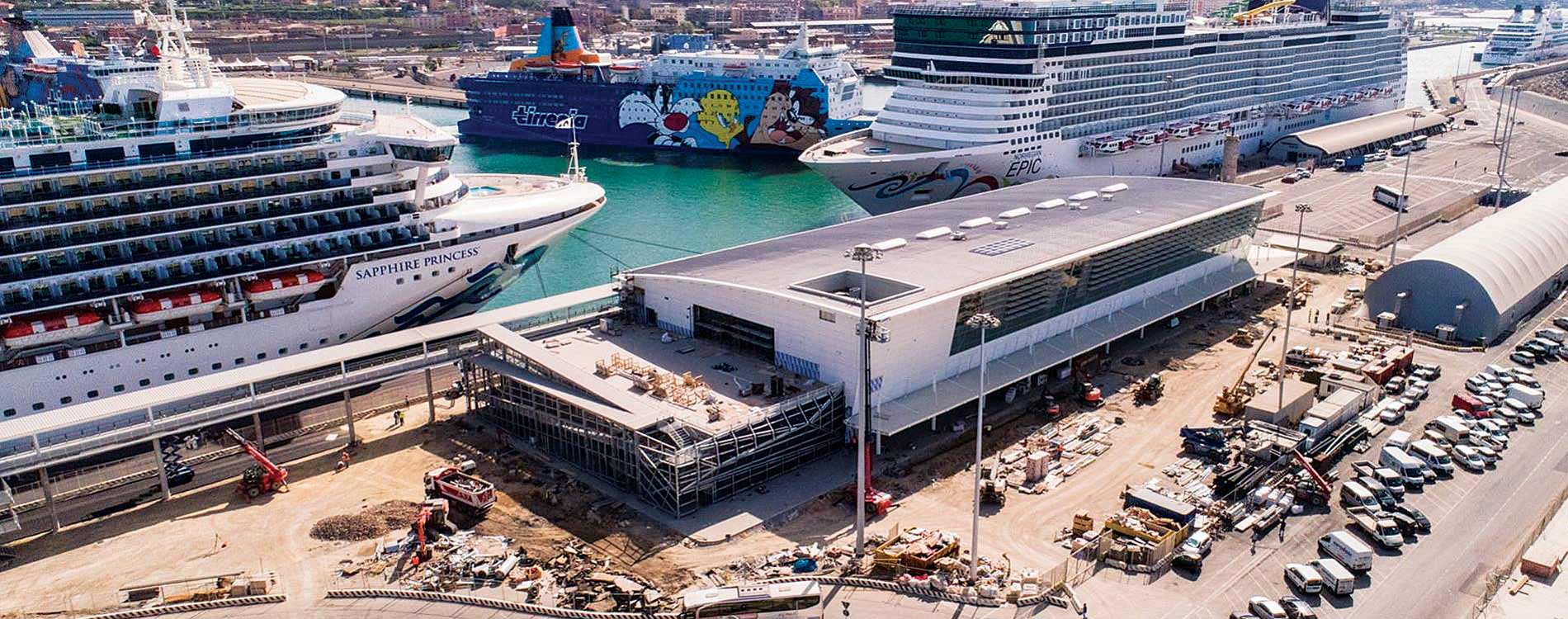
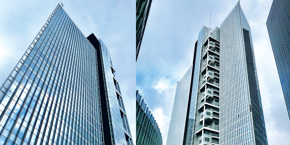
The complex consists of five existing buildings, described below:
• Three tower buildings (B, C, C1) whose load-bearing framework is made of reinforced concrete made up of single walls and beams cast on site, generally in slab thickness, measuring approximately 48.50 m x 14.00 m (C and C1) and 38.60m x 27.70m (B);
• A building with a quadrangular plan (A), in reinforced concrete consisting of a frame system, measuring approximately 42.50 m x 42.50 m;
• A building with an elongated plan, two underground floors and four floors above ground (D), in reinforced concrete consisting of a frame system, measuring approximately 14.00 m x 99.00 m.
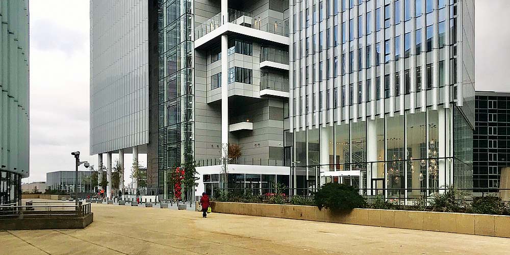
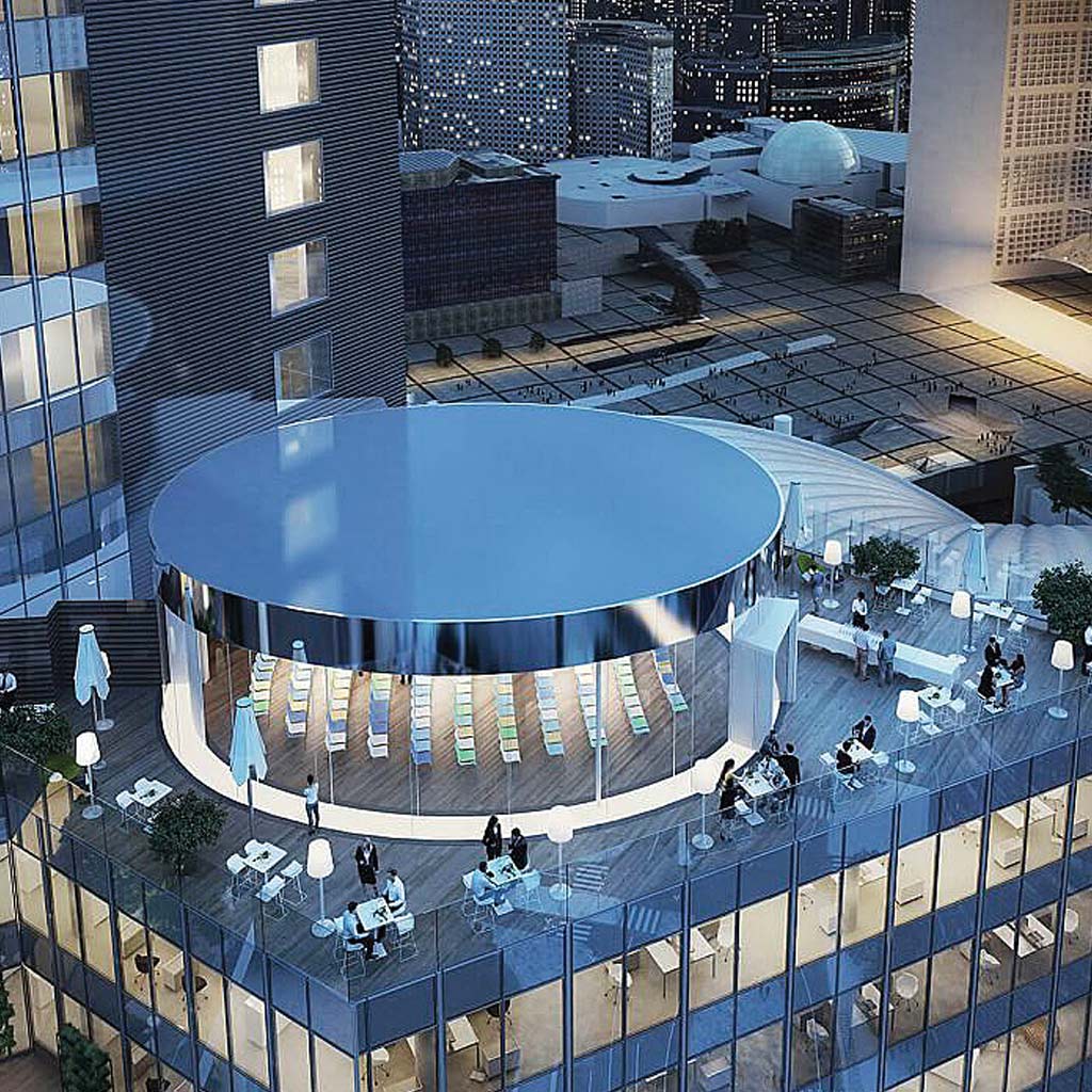
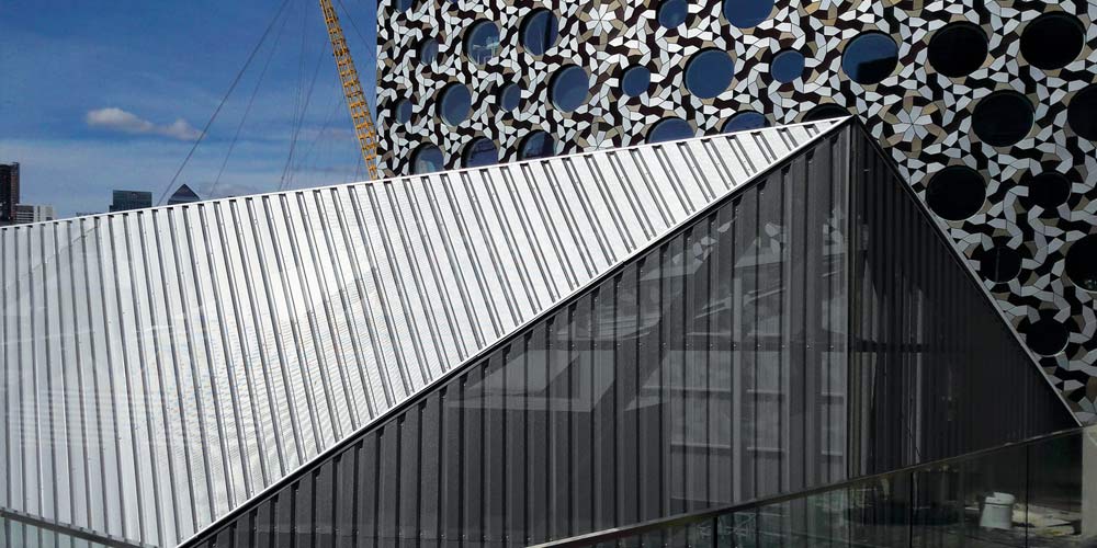
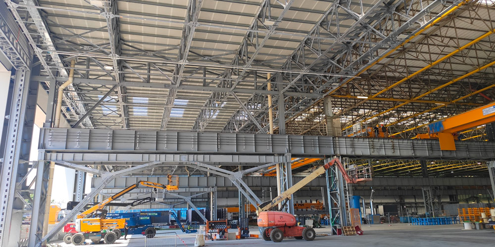
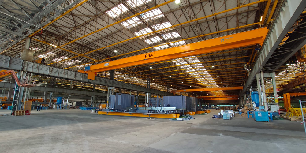
There are also a series of newly built metal carpentry buildings that fit between the buildings previously described, connecting them to each other:
• Buildings G1, G2, G3, G4, G5, two floors;
• Building E, four floors. This, being the central building, has the role of the central nucleus (represents the hub of the entire complex) and therefore has an irregular shape, having to be inserted between the existing surrounding blocks.
The complex consists of five existing buildings, described below:
• Three tower buildings (B, C, C1) whose load-bearing framework is made of reinforced concrete made up of single walls and beams cast on site, generally in slab thickness, measuring approximately 48.50 m x 14.00 m (C and C1) and 38.60m x 27.70m (B);
• A building with a quadrangular plan (A), in reinforced concrete consisting of a frame system, measuring approximately 42.50 m x 42.50 m;
• A building with an elongated plan, two underground floors and four floors above ground (D), in reinforced concrete consisting of a frame system, measuring approximately 14.00 m x 99.00 m.
There are also a series of newly built metal carpentry buildings that fit between the buildings previously described, connecting them to each other:
• Buildings G1, G2, G3, G4, G5, two floors;
• Building E, four floors. This, being the central building, has the role of the central nucleus (represents the hub of the entire complex) and therefore has an irregular shape, having to be inserted between the existing surrounding blocks.