Assembly project of steel structures.
Category: Erections
Services: Executive Design
Period: February 2021 – February 2022
Client: Cimolai S.p.A.

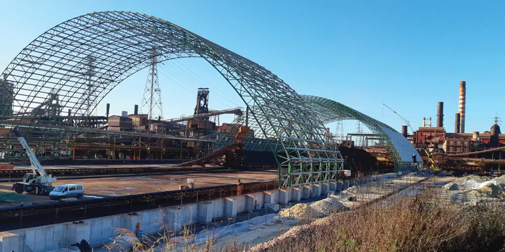
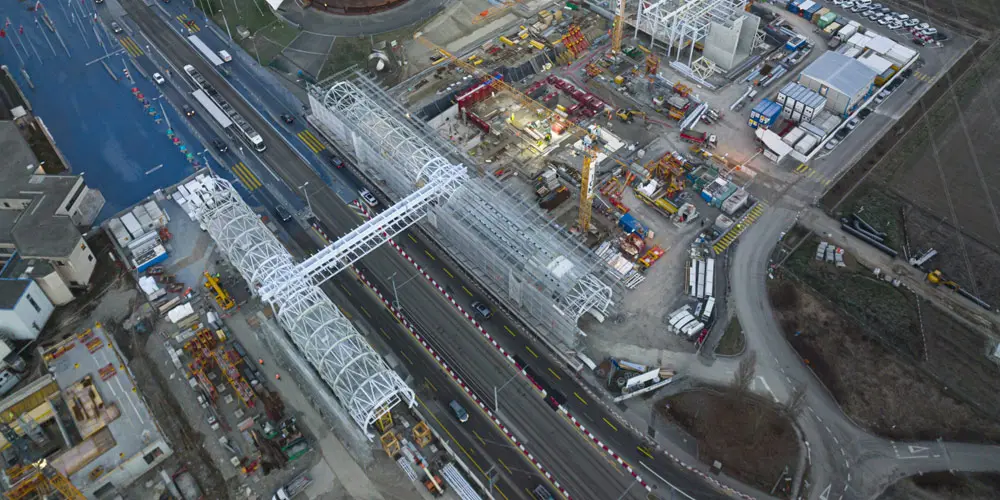
CERN in Geneva: the “Science Gateway”, a structure completely dedicated to education and the dissemination of science. The architecture of Science Gateway, designed by the Renzo Piano Building Workshop design studio, is inspired by the technical installations and underground tunnels of CERN.
CERN in Geneva: the “Science Gateway”, a structure completely dedicated to education and the dissemination of science. The architecture of Science Gateway, designed by the Renzo Piano Building Workshop design studio, is inspired by the technical installations and underground tunnels of CERN.
The project is located within the area of the European Nuclear Research Center and involves the use of approximately 1600t of metal structural work.
Steel Project Engineering specifically dealt with the study of the executive assembly phases of the 3 pavilions, the 2 tubular structures in metal carpentry and the connecting bridge. The construction site aspect was also taken care of, with the relative organization of the construction site areas.

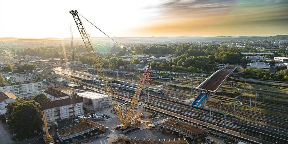
Furthermore, the construction site aspect was taken care of, with the related organization of the construction site areas: this aspect proved to be particularly delicate because of the presence of numerous interfering processes and the consequent evolution of the available areas.
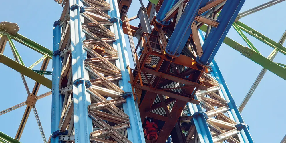
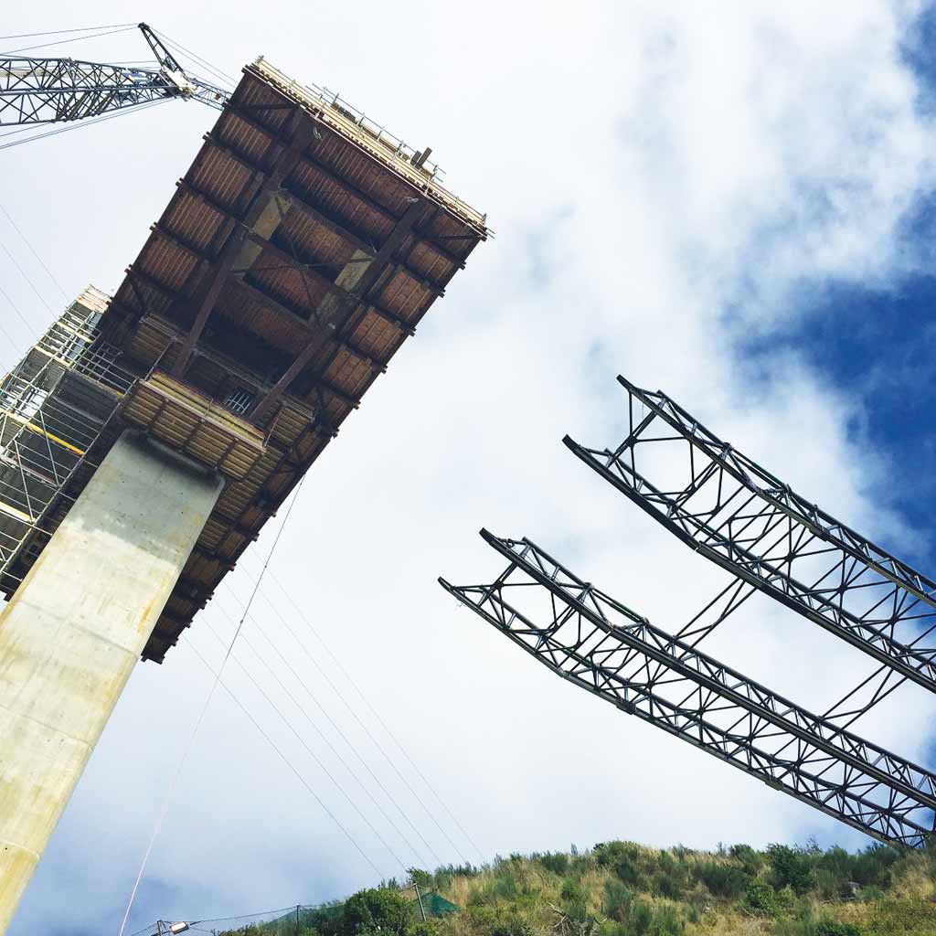
The pavilions, which host exhibitions, practical workshops, shops, restaurants, and also an auditorium, have plan dimensions of 45mx30m (pavilion 1) and 35mx30m (pavilions 2 and 3) and have a structure.
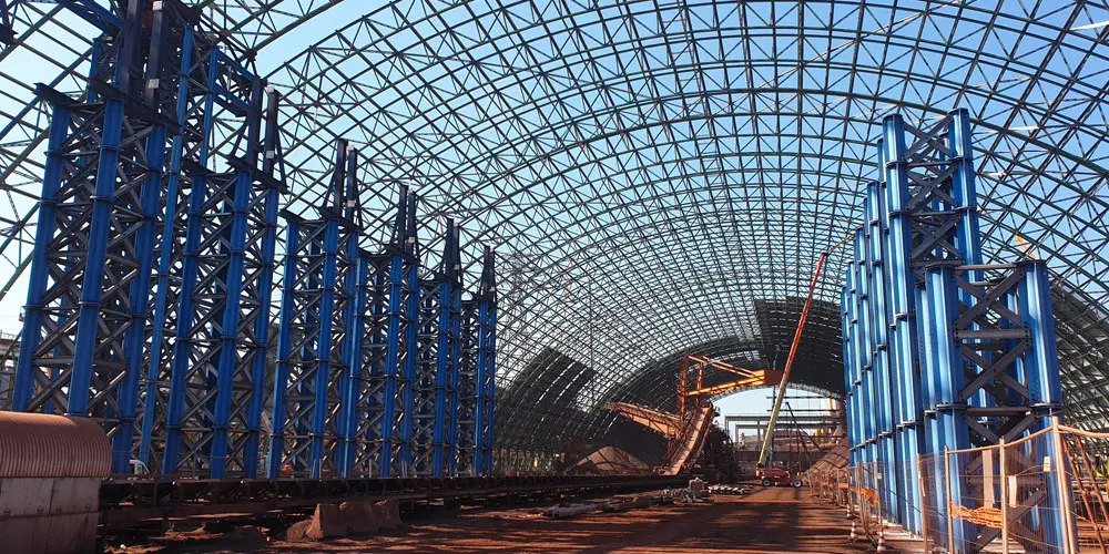
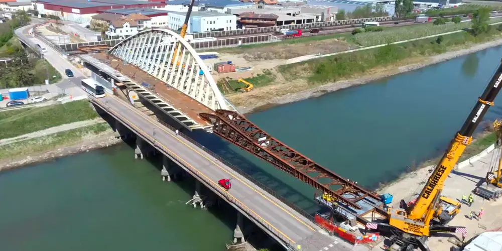
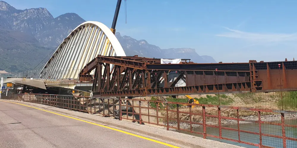
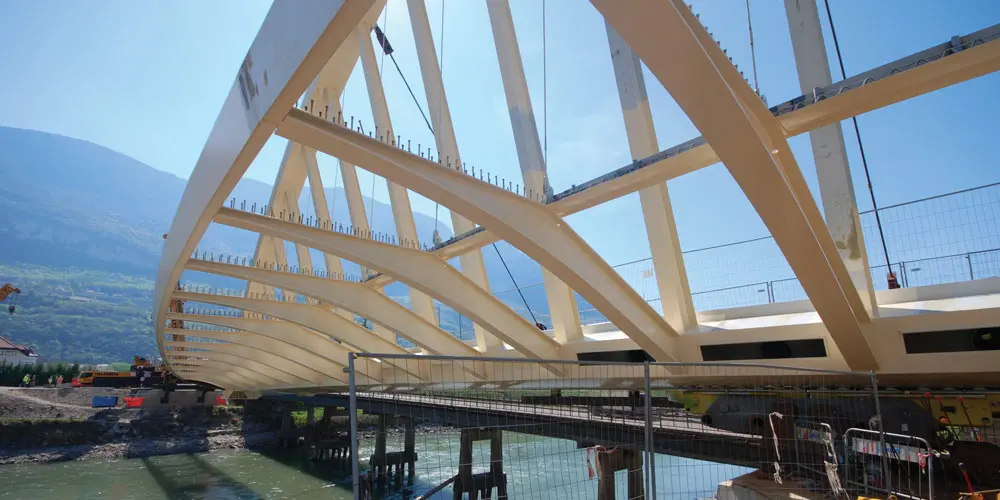
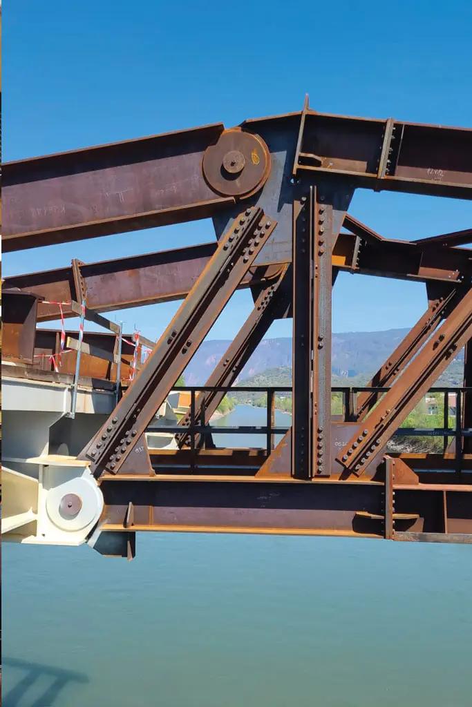
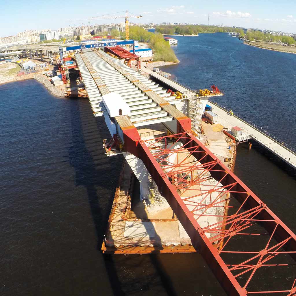
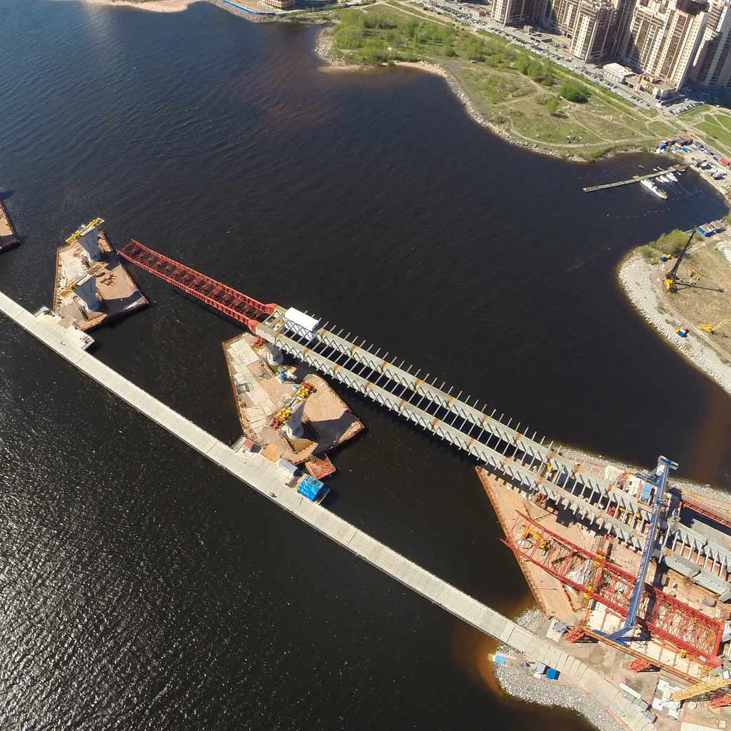
Tubolar structures are two substantially identical structures, which extend over a length of 85m and a width of 10m.
Furthermore, the construction site aspect was taken care of, with the related organization of the construction site areas: this aspect proved to be particularly delicate because of the presence of numerous interfering processes and the consequent evolution of the available areas.
The pavilions, which host exhibitions, practical workshops, shops, restaurants, and also an auditorium, have plan dimensions of 45mx30m (pavilion 1) and 35mx30m (pavilions 2 and 3) and have a structure.
Tubolar structures are two substantially identical structures, which extend over a length of 85m and a width of 10m.
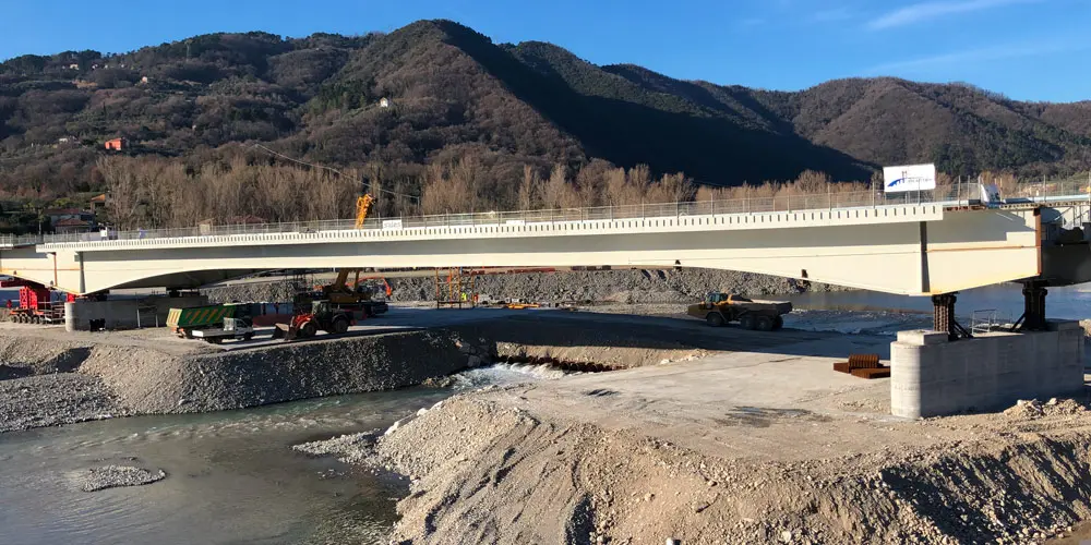
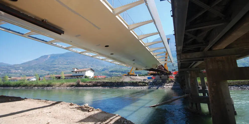
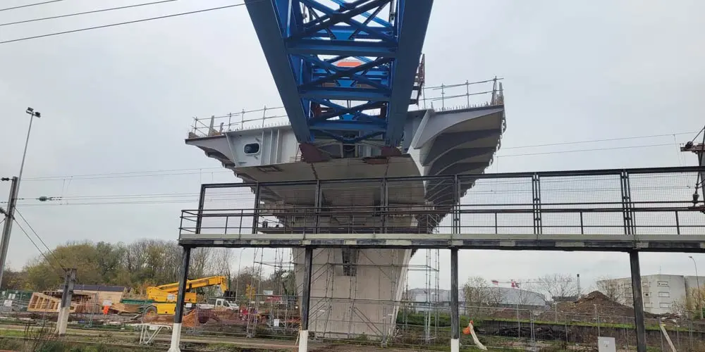
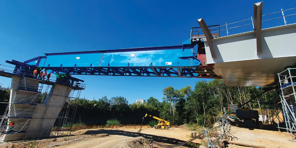
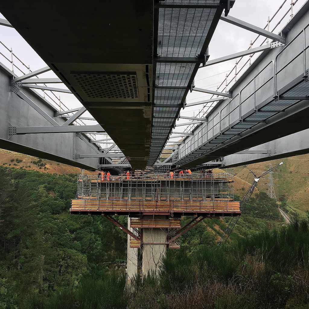
The elevated walkway, which rises over 6m above the ground, in addition to allowing the crossing of the tram line, guarantees the connection between the various buildings.
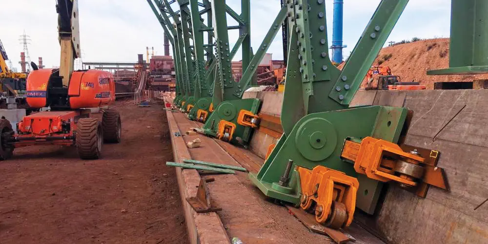
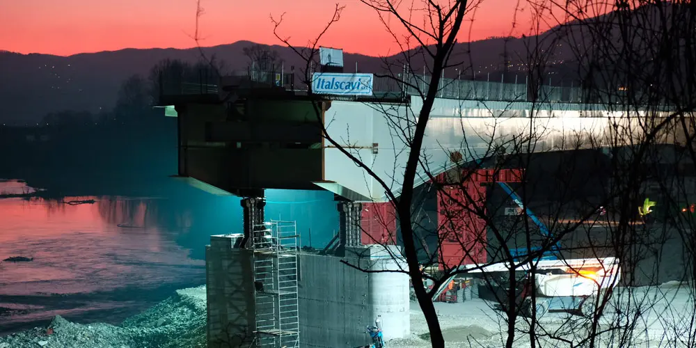
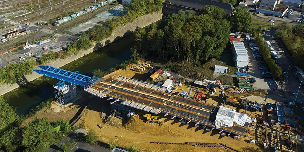
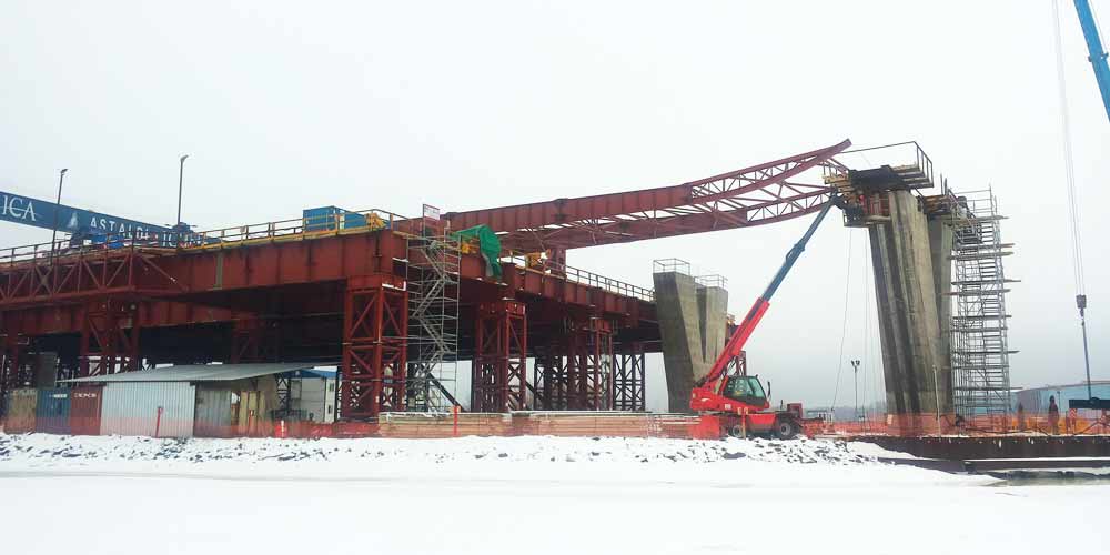
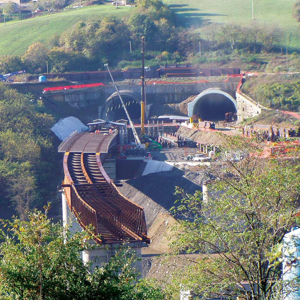
The construction site area was carefully studied during the various phases of the construction site’s life: the storage and assembly areas, the internal construction site roads, the areas dedicated to lifting machinery were always determined taking into account and safeguarding regular activity of the other processes that took place in the surrounding areas.

The elevated walkway, which rises over 6m above the ground, in addition to allowing the crossing of the tram line, guarantees the connection between the various buildings.
The construction site area was carefully studied during the various phases of the construction site’s life: the storage and assembly areas, the internal construction site roads, the areas dedicated to lifting machinery were always determined taking into account and safeguarding regular activity of the other processes that took place in the surrounding areas.

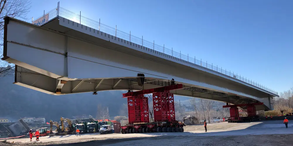
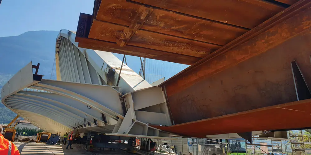
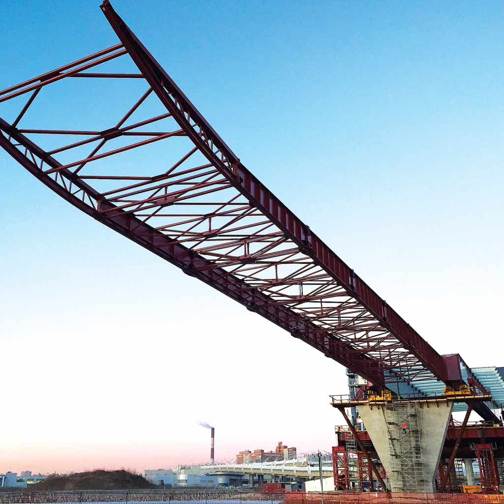
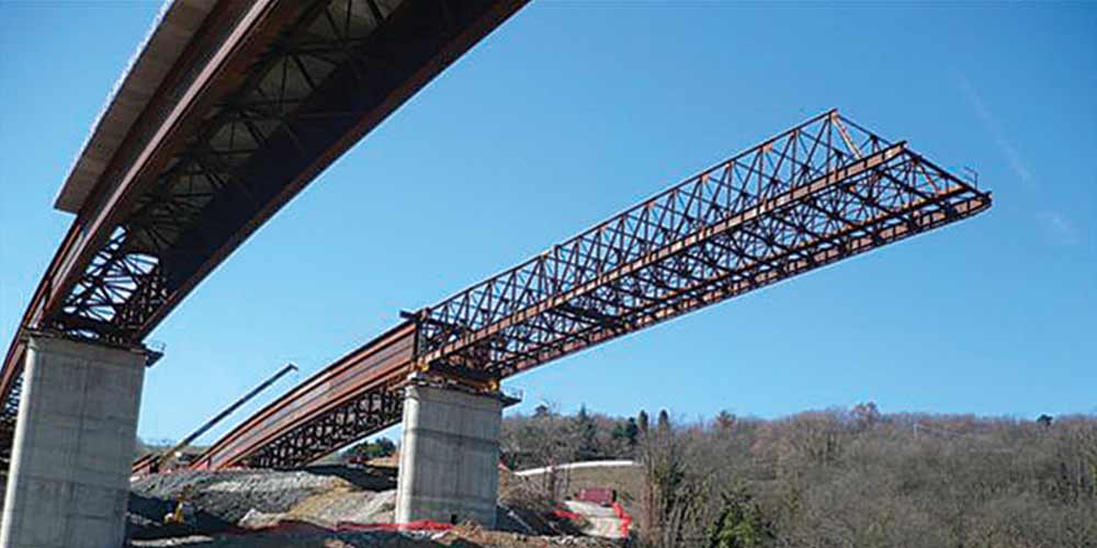
Assembly began with the installation of the tubular structures and the section of walkway between them. We then moved on to assembling the pavilions and then completing the connecting walkway, paying particular attention to the static scheme which included half-joint. The sections of walkway above the pavilions were positioned at the same time as the pavilions themselves in light of the interference otherwise present with the roofs. In any case, maximum prefabrication was favored and, compatibly with the capacities of the construction site cranes, the bridge frames, the walkway macro segments and some pavilion frames were pre-assembled on the ground and then raised to heights.
We have also designed the various assembly equipment such as temporary piles, eyebolts and lifting frames, temporary supports etc.