Erection design of a cycle-pedestrian on the river Ombrone.
Category: Erections
Services: Final Design
Period: June 2014 – October 2014
Client: Bit S.p.a.
Amount: 1.399.601,87 € (Categories IXb, IXc, VIa)
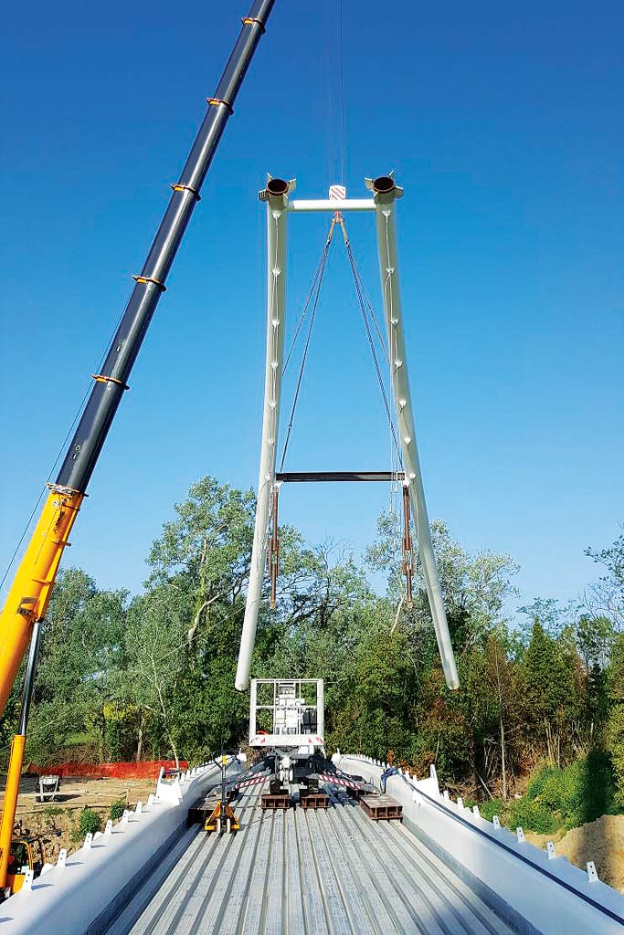
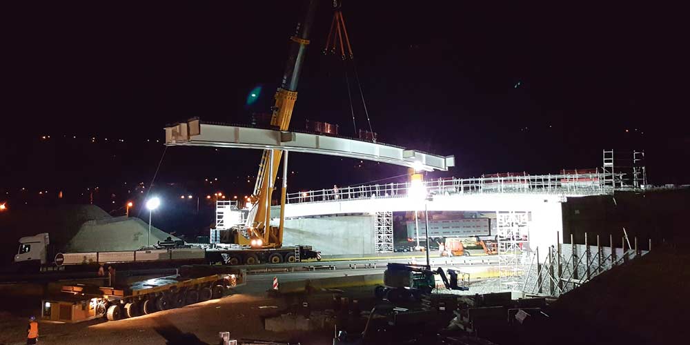
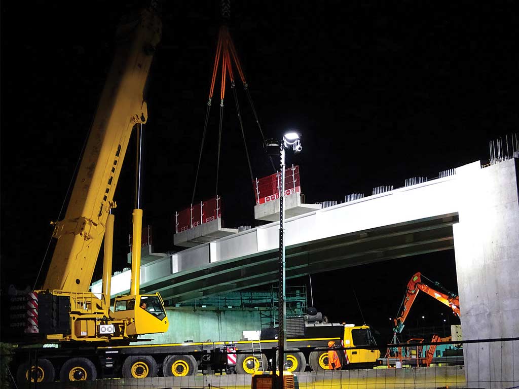
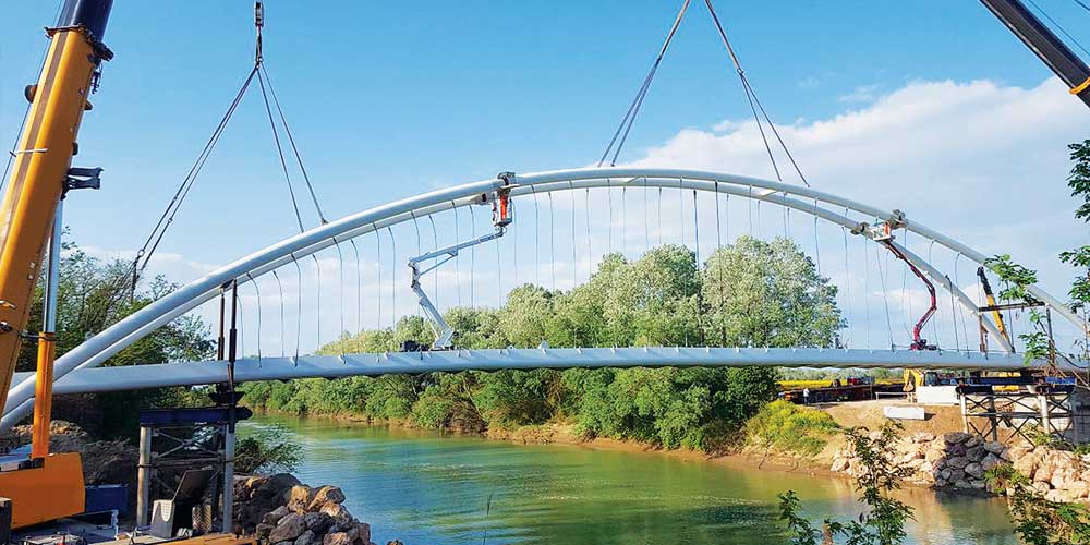
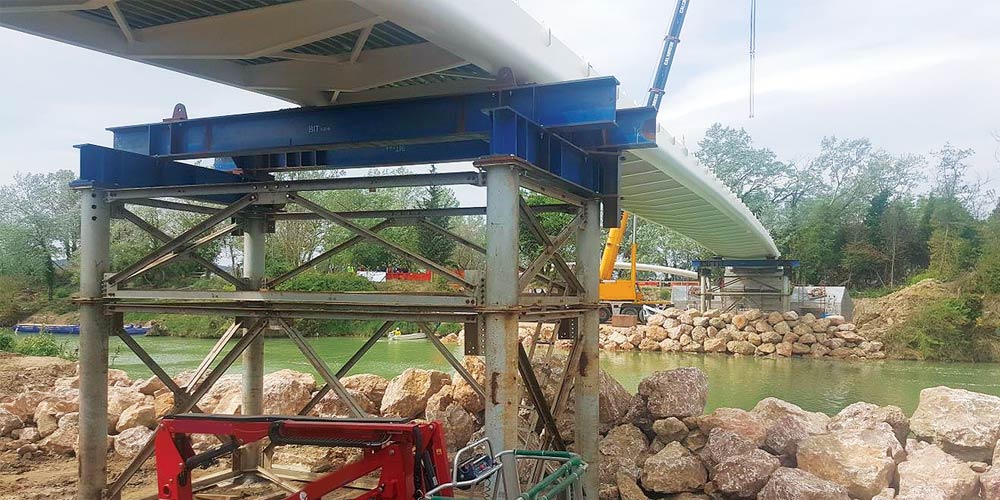
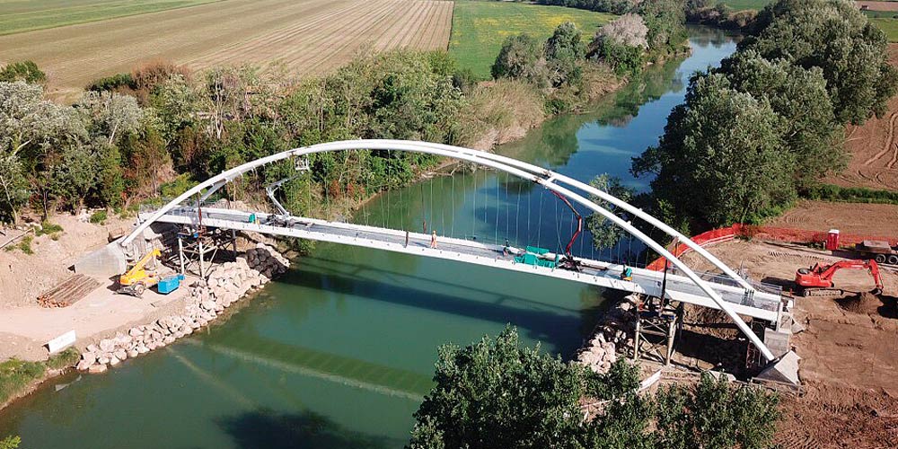
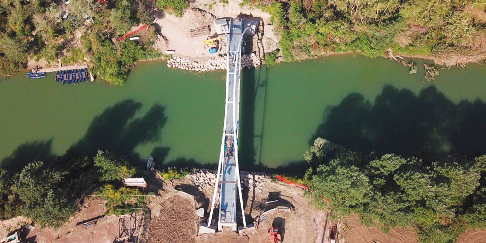
The final design of a steel arched cycle-pedestrian walkway. The deck is made with two lateral beams, supported by the tubular arches by means of a suspension system, with hangers converging towards the center.
The final design of a steel arched cycle-pedestrian walkway. The deck is made with two lateral beams, supported by the tubular arches by means of a suspension system, with hangers converging towards the center.
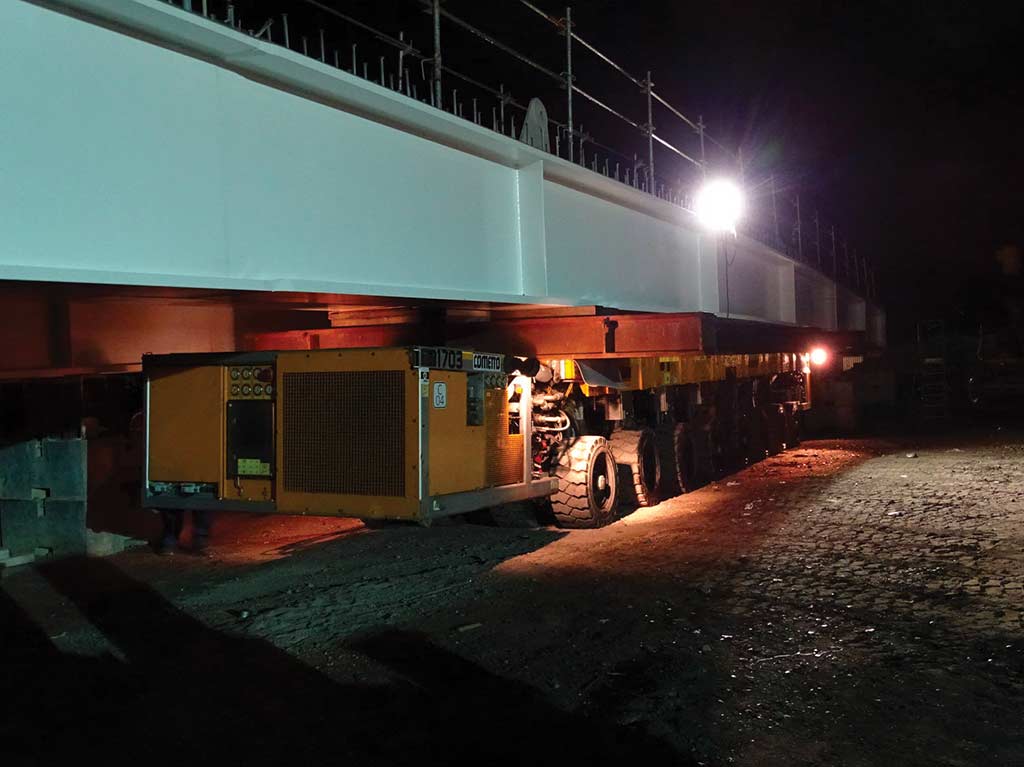
The main deck beams, made with a C-shaped cross section composed of bent metal sheets by welding, are connected with metal crosspieces in a double T section of variable height, tapered at the connection to the chain beam and arranged at the pitch of the hangers, i.e. every 2 m.
The main deck beams, made with a C-shaped cross section composed of bent metal sheets by welding, are connected with metal crosspieces in a double T section of variable height, tapered at the connection to the chain beam and arranged at the pitch of the hangers, i.e. every 2 m.
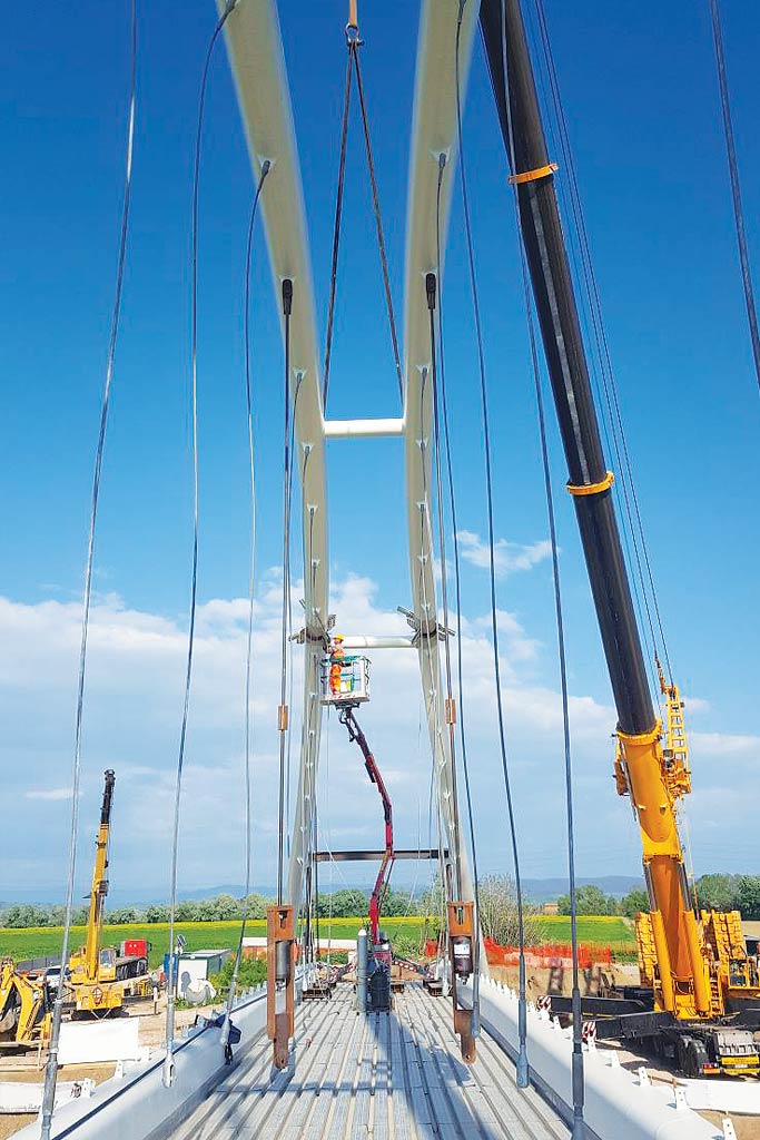
The hangers are made with full locked coil ropes with a theoretical diameter of 20 mm connected to the deck with an adjustable fork terminal and to the arch with a fixed fork terminal.
The hangers are made with full locked coil ropes with a theoretical diameter of 20 mm connected to the deck with an adjustable fork terminal and to the arch with a fixed fork terminal.
The decking is made with a 12 cm thick corrugated sheet slab resisting in the longitudinal direction between two transverse beams.
The decking is made with a 12 cm thick corrugated sheet slab resisting in the longitudinal direction between two transverse beams.
The main geometric features of the work are:
• Walkway span approx.72 m
• Height of the arches about 15.00 m
• Effective deck width m 3.50
The main geometric features of the work are:
• Walkway span approx.72 m
• Height of the arches about 15.00 m
• Effective deck width m 3.50