Launching plan for the metal viaducts of the Yard 3.1
Category: Launchings
Services: Final design during launching
Period: October 2014 – February 2015
Client: VCS Monthaz – Astaldi
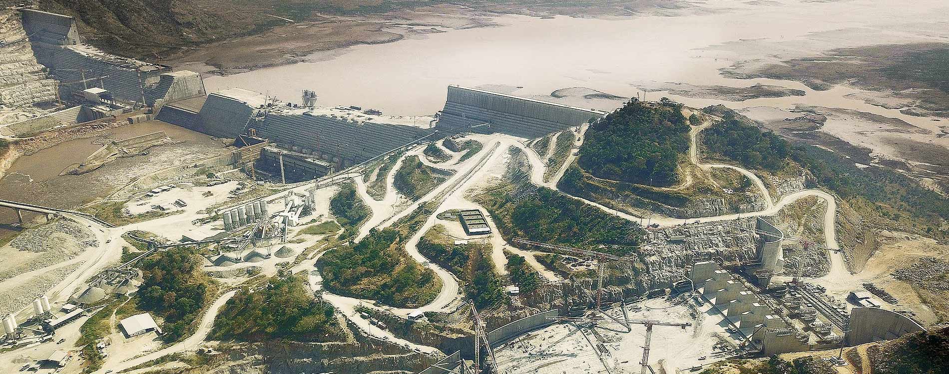
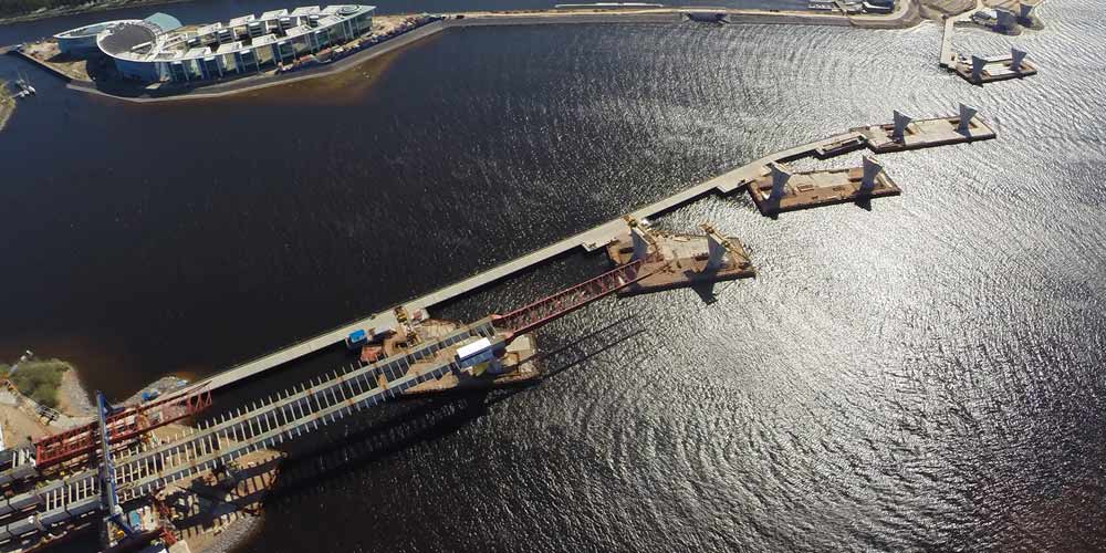
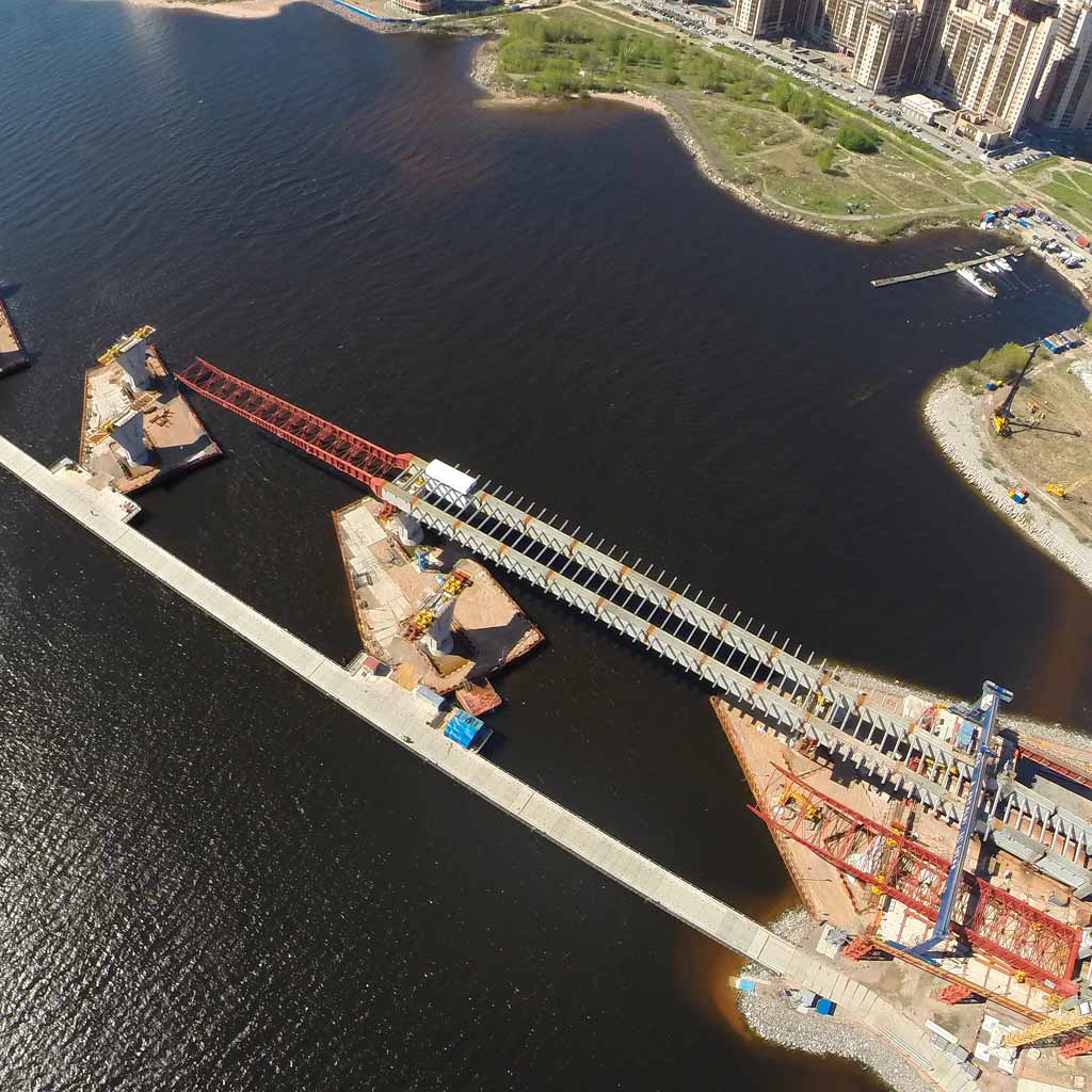
La nuova tangenziale esterna di San Pietroburgo è un’opera di dimensioni ciclopiche che nasce per risolvere il congestionamento del traffico stradale nel centro città: l’orografia della città, costituita da un agglomerato di isole collegate fra loro da ponti stradali, ha reso necessario il ricorso a un tracciato esterno alternativo alla viabilità ordinaria, realizzato in buona parte direttamente sul mare.
La nuova tangenziale esterna di San Pietroburgo è un’opera di dimensioni ciclopiche che nasce per risolvere il congestionamento del traffico stradale nel centro città: l’orografia della città, costituita da un agglomerato di isole collegate fra loro da ponti stradali, ha reso necessario il ricorso a un tracciato esterno alternativo alla viabilità ordinaria, realizzato in buona parte direttamente sul mare.
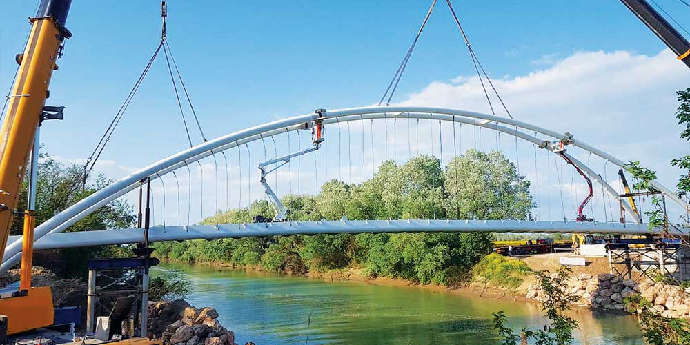
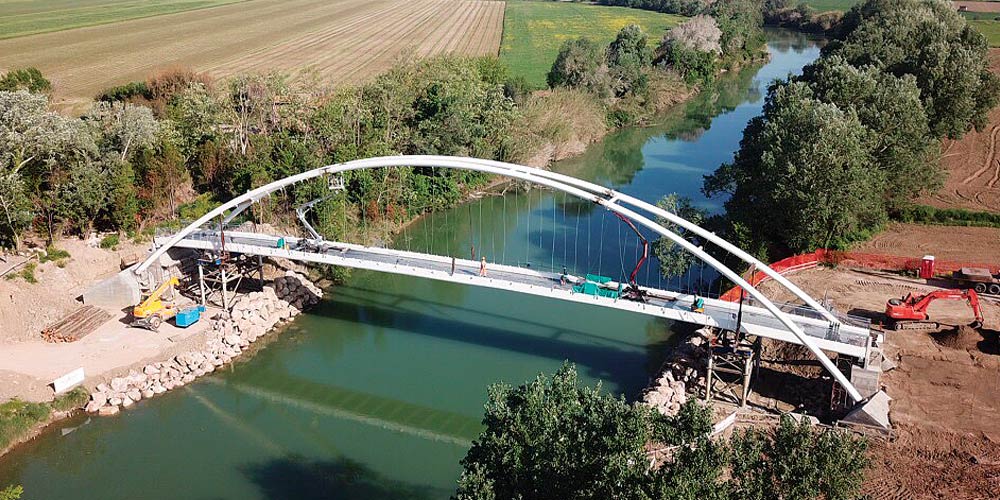
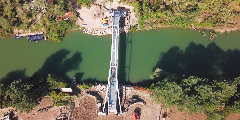
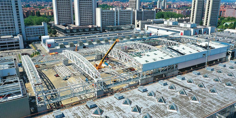
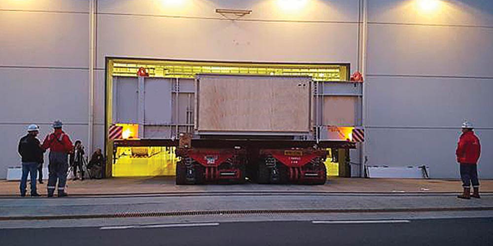
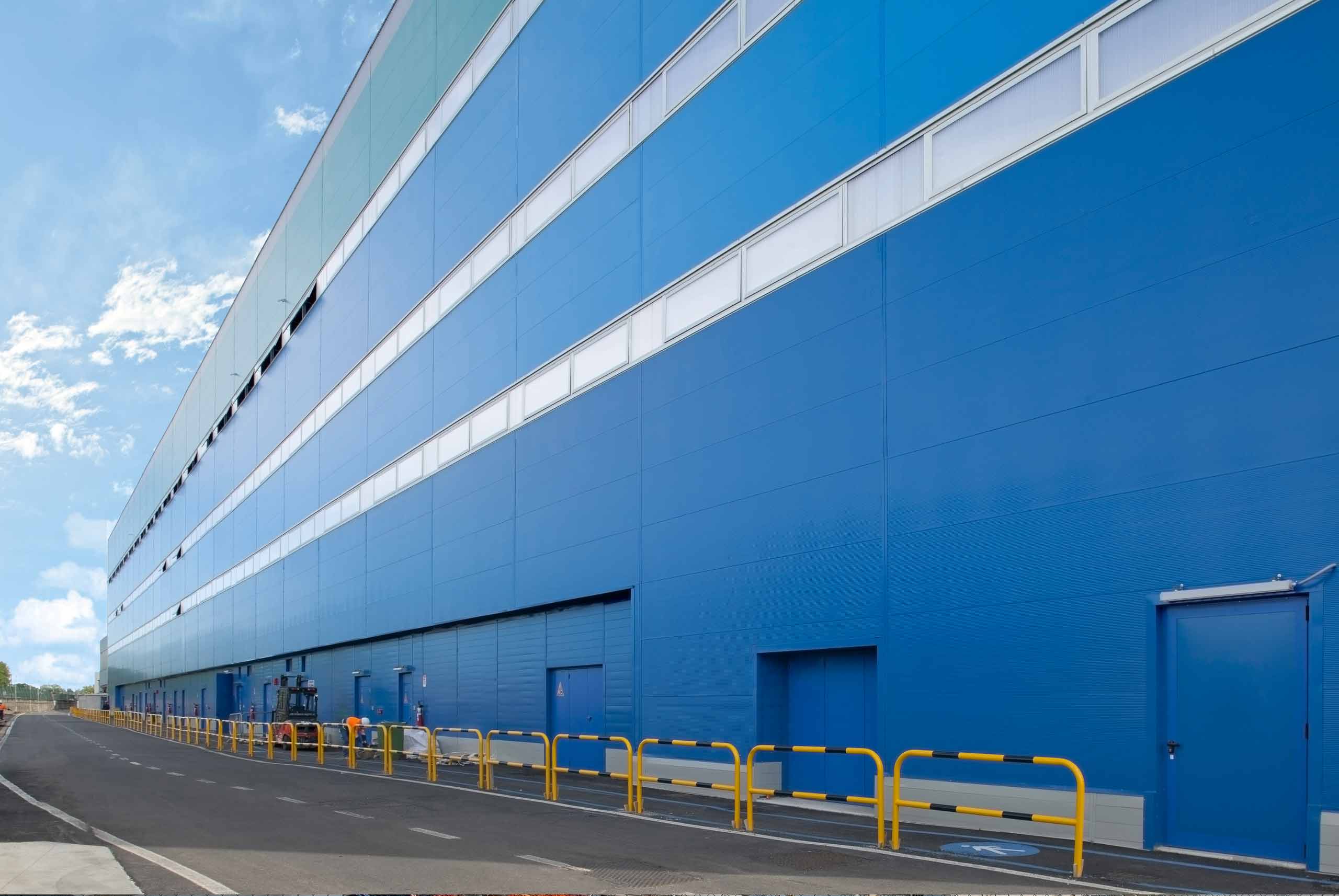
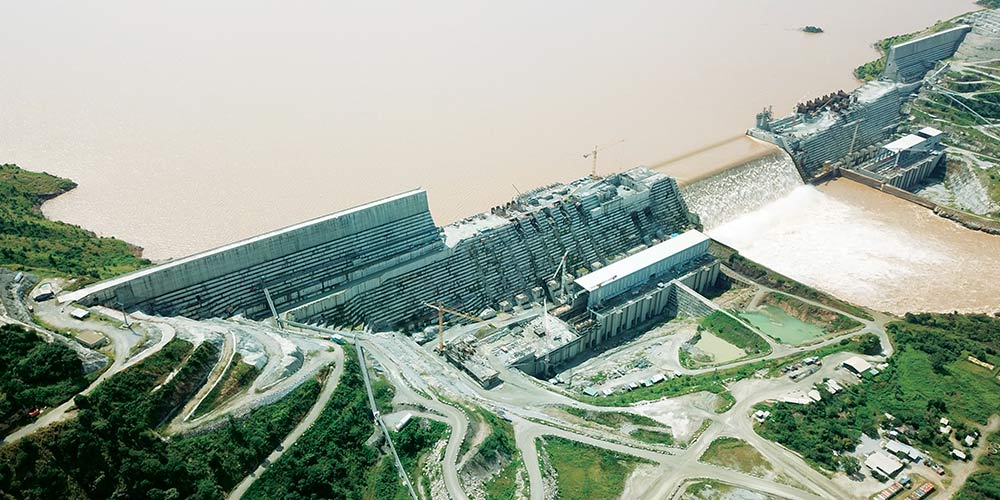
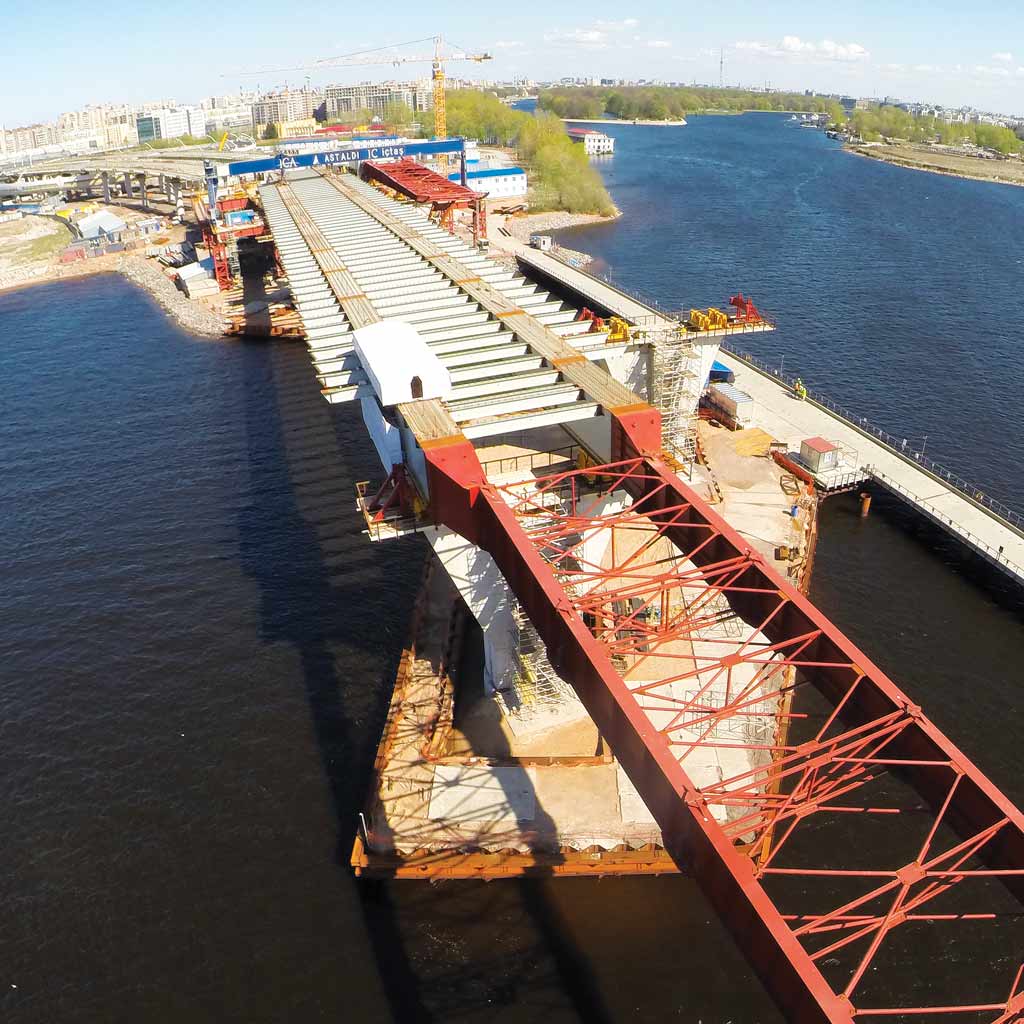
Dei quasi 12 km costituenti la sezione centrale del WHSD, oggetto del presente appalto, quasi 10 sono costituite da strutture off shore: 2 ponti strallati, un tunnel sotterraneo e una serie di impalcati a travata realizzati direttamente in mare e per tale ragione montati con varo frontale.
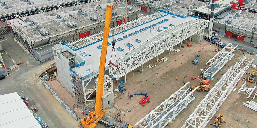
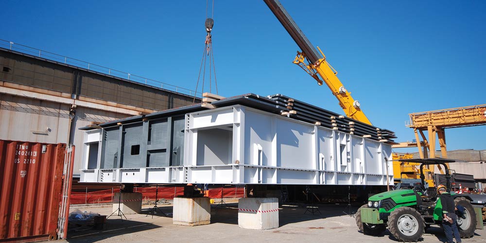
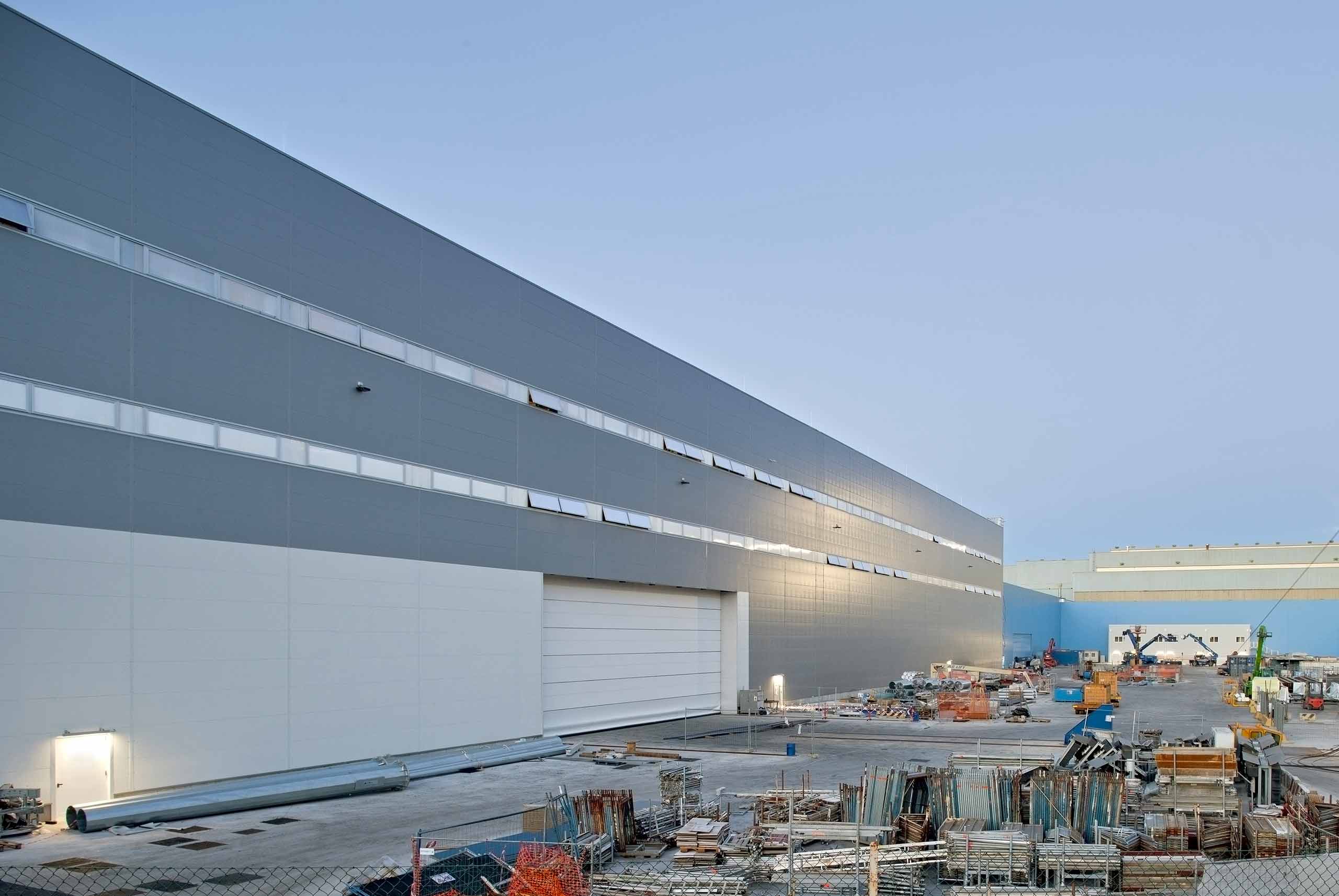
L’oggetto del nostro intervento ha riguardato i viadotti stradali in struttura mista della carreggiata sinistra e destra per la Yard 3.1, realizzati con travate continua di 5 campate e luci pari a 105 m x 4 + 108 m. Le attività svolte hanno riguardato la validazione del progetto esecutivo di varo fornito dal general contractor e la redazione del piano di varo da utilizzare operativamente in cantiere durante le fasi di assemblaggi e varo. Abbiamo poi fornito assistenza al cantiere per l’approvazione della documentazione a corredo del varo e durante le fasi di varo e di calaggio degli impalcati metallici.
Dei quasi 12 km costituenti la sezione centrale del WHSD, oggetto del presente appalto, quasi 10 sono costituite da strutture off shore: 2 ponti strallati, un tunnel sotterraneo e una serie di impalcati a travata realizzati direttamente in mare e per tale ragione montati con varo frontale.
L’oggetto del nostro intervento ha riguardato i viadotti stradali in struttura mista della carreggiata sinistra e destra per la Yard 3.1, realizzati con travate continua di 5 campate e luci pari a 105 m x 4 + 108 m. Le attività svolte hanno riguardato la validazione del progetto esecutivo di varo fornito dal general contractor e la redazione del piano di varo da utilizzare operativamente in cantiere durante le fasi di assemblaggi e varo. Abbiamo poi fornito assistenza al cantiere per l’approvazione della documentazione a corredo del varo e durante le fasi di varo e di calaggio degli impalcati metallici.
IL PROGETTO
Conoscenza dei sistemi di montaggio.
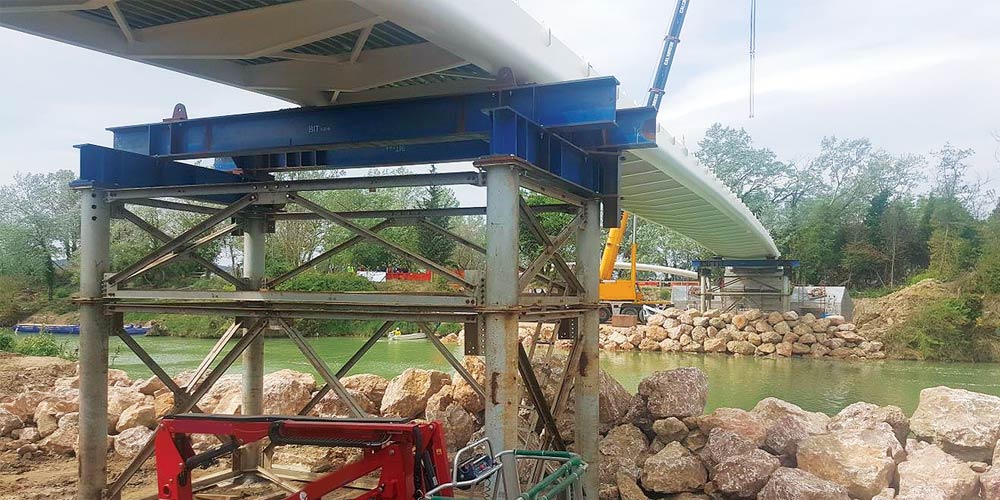
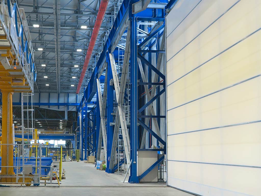
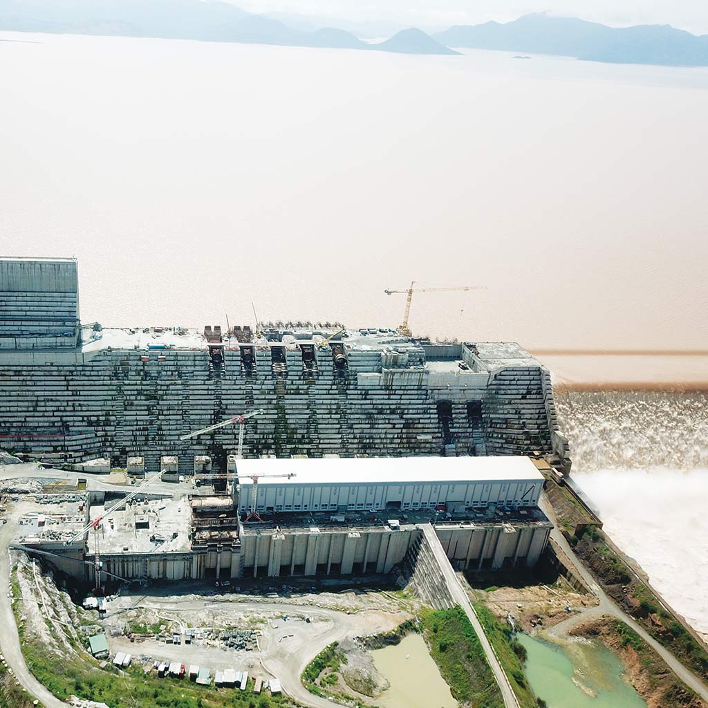
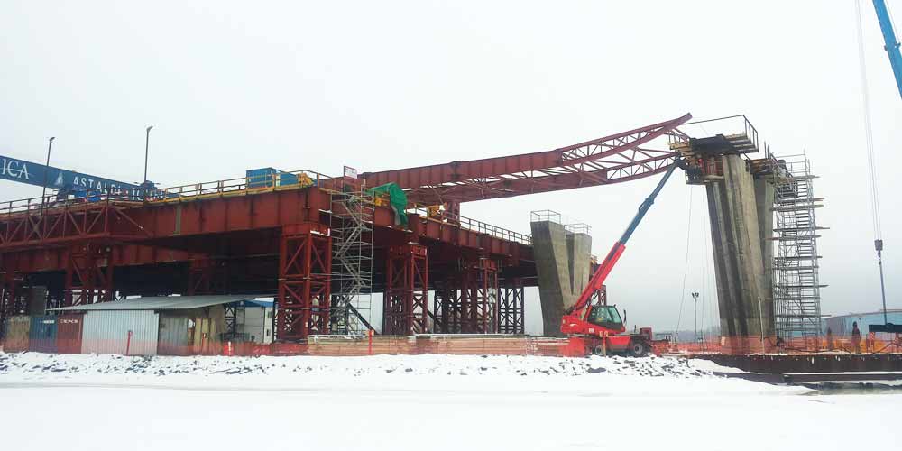
In ragione di un varo attuato interamente su pile situate in riva al mare, il montaggio è stato particolarmente complesso su molti fronti, legati:
- alla logistica del cantiere
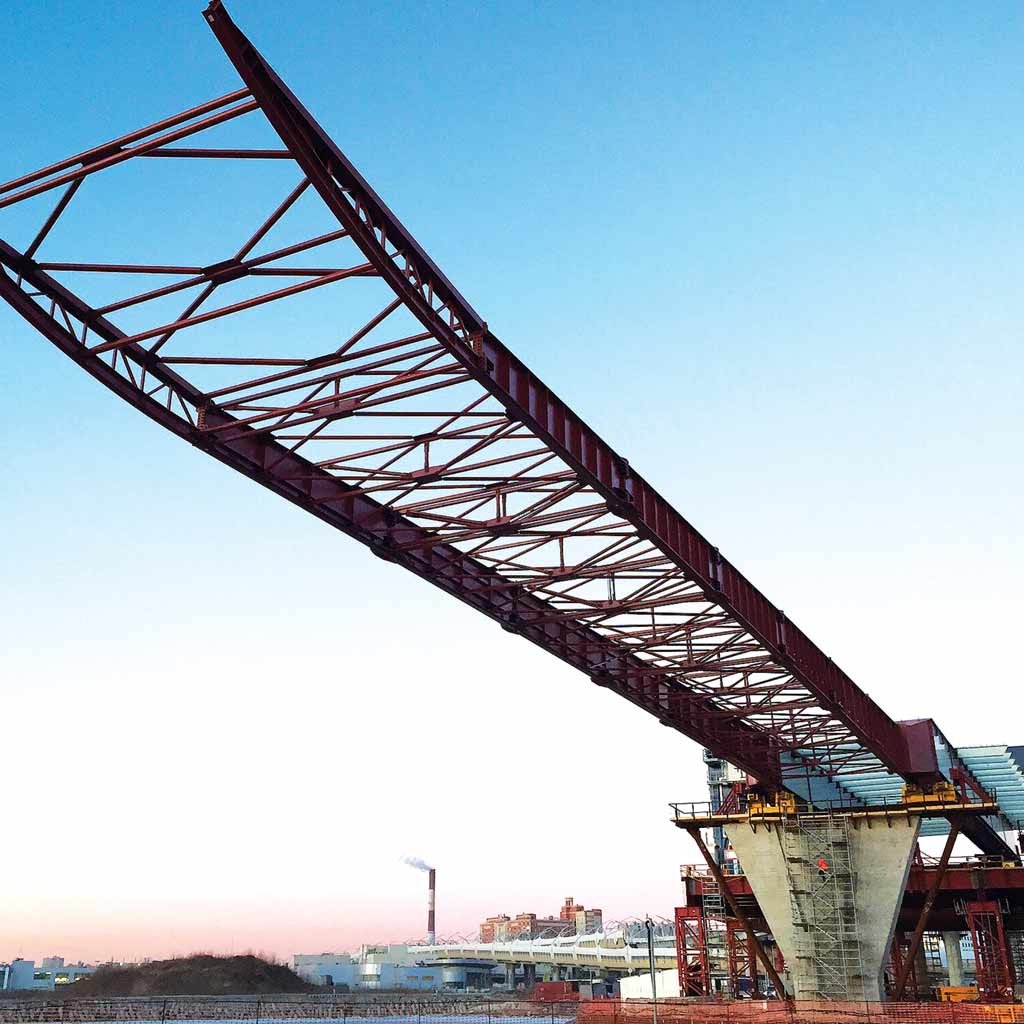
- alla tipologia di impalcato varato di punta nonostante un tracciato planimetrico in doppia clotoide
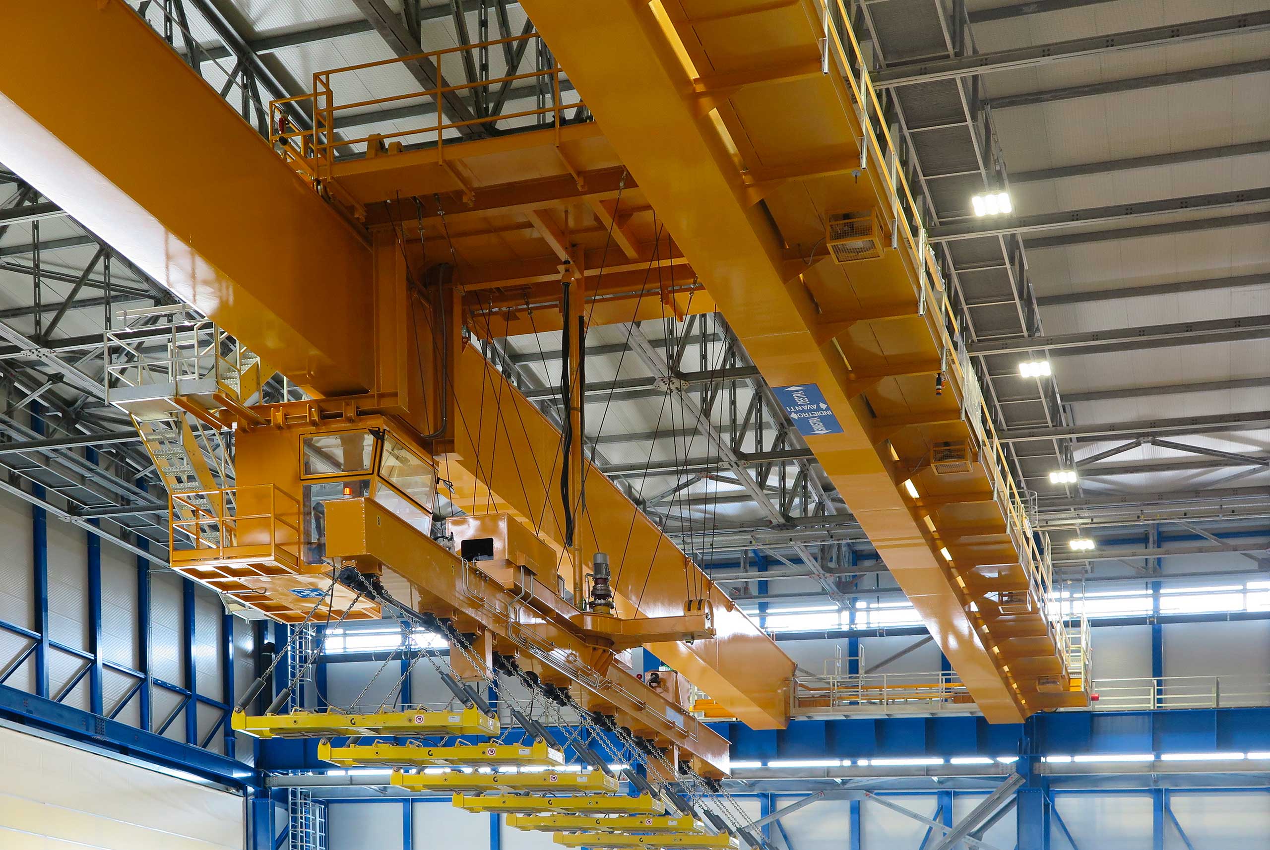
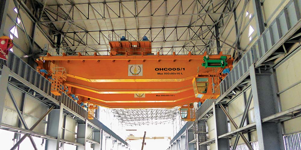
- alla tipologia di attrezzature previste dal progetto di varo del GC, ossia rulliere idrauliche per l’adattamento alla variabilità della livelletta e la pesatura delle reazioni dotate anche di sistemi di traslazione in orizzontale per assecondare l’andamento planimetrico del tracciato.
Le attività di validazione del progetto hanno consentito da un lato di verificare la correttezza delle assunzioni fatte nel progetto del GC e dall’altro di completare le parti in cui tale progetto non forniva le informazioni necessarie al cantiere per le procedure operative e di controllo delle diverse fasi di avanzamento del treno di varo.
La conoscenza approfondita dei sistemi di varo e delle relative attrezzature ci ha permesso di tradurre in elaborati operativi per il cantiere le informazioni del progetto di varo, mettendo a disposizione dell’equipe di montaggio un documento esaustivo delle procedure operative e dei processi di controllo durante le fasi di varo, in cui si evidenziano le operazioni e i passaggi più critici e si integrano le procedure nelle parti in cui il progetto del GC non risultava esaustivo.