CERN - The “Science Gateway”

CERN – The “Science Gateway”

Assembly project of steel structures.

Category: Erections
Services: Executive Design
Period: February 2021 – February 2022
Client: Cimolai S.p.A.

CERN - The “Science Gateway”

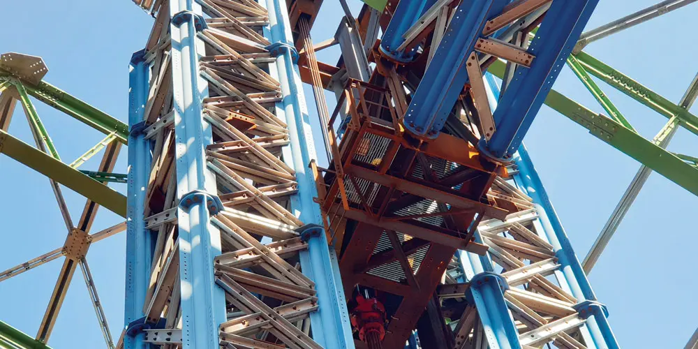
CERN in Geneva: the “Science Gateway”, a structure completely dedicated to education and the dissemination of science. The architecture of Science Gateway, designed by the Renzo Piano Building Workshop design studio, is inspired by the technical installations and underground tunnels of CERN.

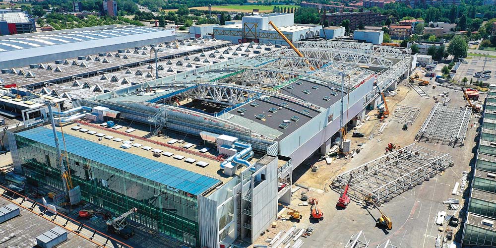
The project is located within the area of the European Nuclear Research Center and involves the use of approximately 1600t of metal structural work.
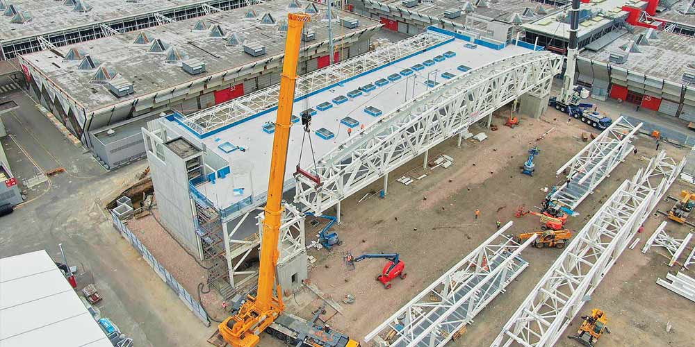
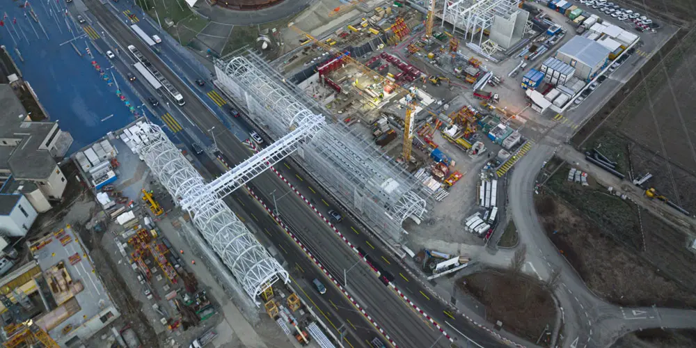
Steel Project Engineering specifically dealt with the study of the executive assembly phases of the 3 pavilions, the 2 tubular structures in metal carpentry and the connecting bridge. The construction site aspect was also taken care of, with the relative organization of the construction site areas.

CERN - The “Science Gateway”

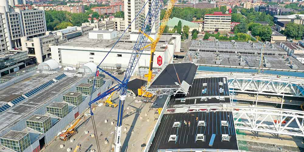
Furthermore, the construction site aspect was taken care of, with the related organization of the construction site areas: this aspect proved to be particularly delicate because of the presence of numerous interfering processes and the consequent evolution of the available areas.
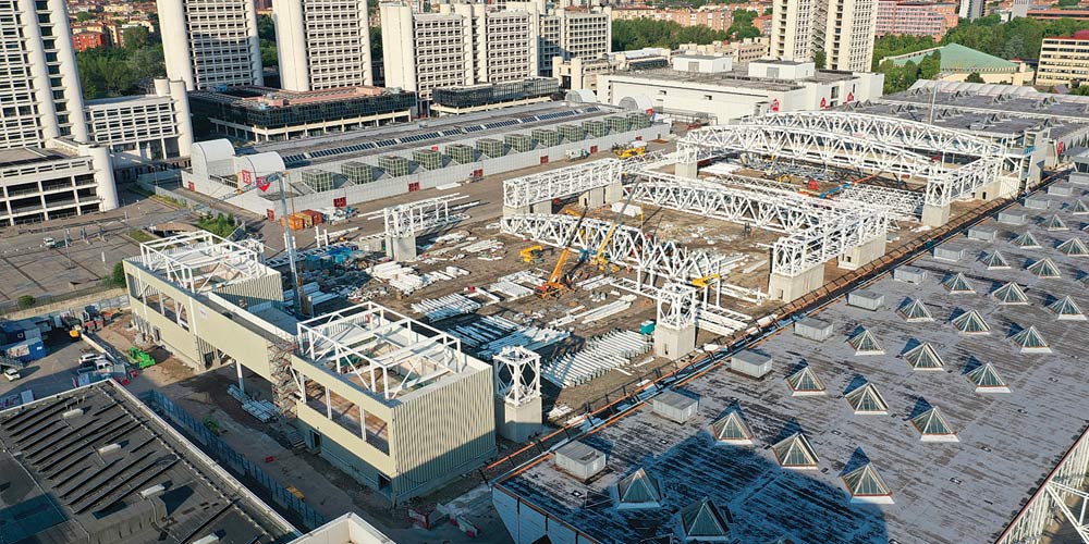
The pavilions, which host exhibitions, practical workshops, shops, restaurants, and also an auditorium, have plan dimensions of 45mx30m (pavilion 1) and 35mx30m (pavilions 2 and 3) and have a structure.
Tubolar structures are two substantially identical structures, which extend over a length of 85m and a width of 10m.

The elevated walkway, which rises over 6m above the ground, in addition to allowing the crossing of the tram line, guarantees the connection between the various buildings.
The construction site area was carefully studied during the various phases of the construction site’s life: the storage and assembly areas, the internal construction site roads, the areas dedicated to lifting machinery were always determined taking into account and safeguarding regular activity of the other processes that took place in the surrounding areas.

CERN - The “Science Gateway”

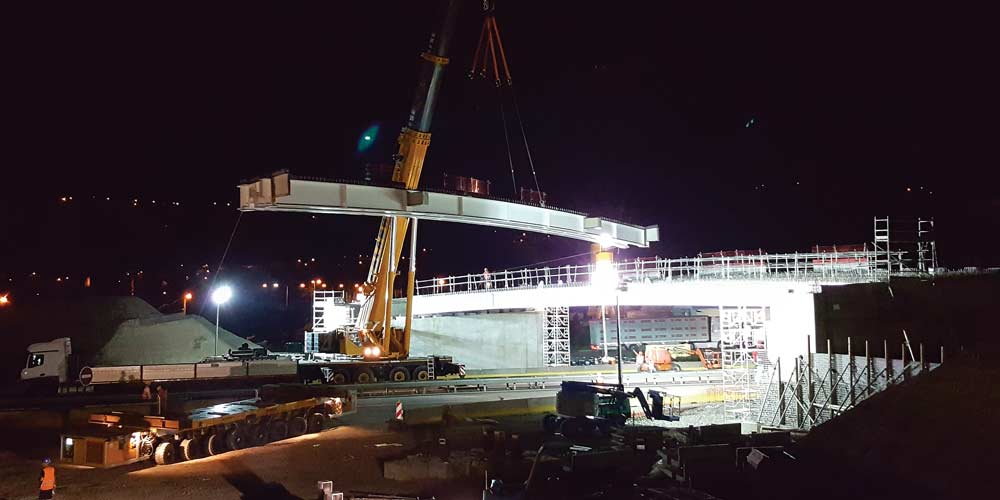
Assembly began with the installation of the tubular structures and the section of walkway between them. We then moved on to assembling the pavilions and then completing the connecting walkway, paying particular attention to the static scheme which included half-joint. The sections of walkway above the pavilions were positioned at the same time as the pavilions themselves in light of the interference otherwise present with the roofs. In any case, maximum prefabrication was favored and, compatibly with the capacities of the construction site cranes, the bridge frames, the walkway macro segments and some pavilion frames were pre-assembled on the ground and then raised to heights.
We have also designed the various assembly equipment such as temporary piles, eyebolts and lifting frames, temporary supports etc.
CERN - The “Science Gateway”

Assembly began with the installation of the tubular structures and the section of walkway between them. We then moved on to assembling the pavilions and then completing the connecting walkway, paying particular attention to the static scheme which included half-joint. The sections of walkway above the pavilions were positioned at the same time as the pavilions themselves in light of the interference otherwise present with the roofs. In any case, maximum prefabrication was favored and, compatibly with the capacities of the construction site cranes, the bridge frames, the walkway macro segments and some pavilion frames were pre-assembled on the ground and then raised to heights.
We have also designed the various assembly equipment such as temporary piles, eyebolts and lifting frames, temporary supports etc.
Parco Materie Prime

Raw materials park

Erection design of steel structures.

Category: Erections
Services: Erection Design
Period: February 2021 – February 2022
Client: Fincantieri Infrastructure S.p.A.

Parco Materie Prime

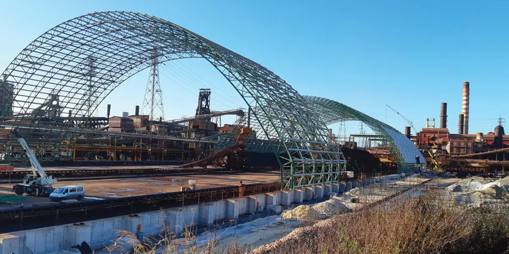
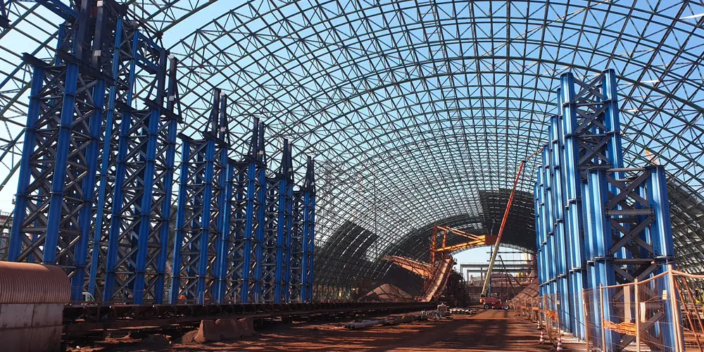
The safe confinement steel structure for the OMO (raw materials) park located inside the “Acciaierie d’Italia” factory in Taranto has plan dimensions of 110 x 385m and is made up of 63 trussed arches, spaced by 6.20 m and with a maximum height of approximately 42m.
Because of the erection phases, the structure was divided into 9 macro-modules, each consisting of 7 arches. Once the central segments of each macro-module are assembled, they are raised by means of 4 strand jacks connected to a horizontal truss beam which can slide between vertical guides placed on the lifting towers.

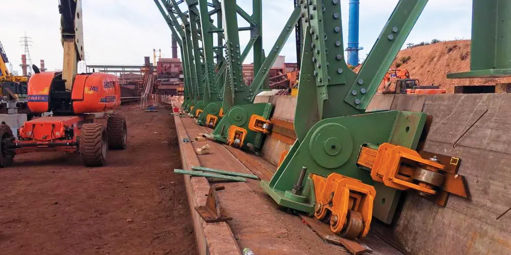
Once the assembly of a single macro-module was completed, it was placed on trolleys and then pushed towards its final position by means of a couple of strand jacks.

Parco Materie Prime
Parco Materie Prime

Once the assembly of a single macro-module was completed, it was placed on trolleys and then pushed towards its final position by means of a couple of strand jacks.

Parco Materie Prime
Ponte sul fiume Magra

Bridge on the Magra river

Projet de montage du nouveau pont sur la rivière Magra.

Category: Road bridges
Services: Erection Design
Period: October 2021 – February 2022
Client: Fincantieri Infrastructure S.p.A.

Ponte sul fiume Magra

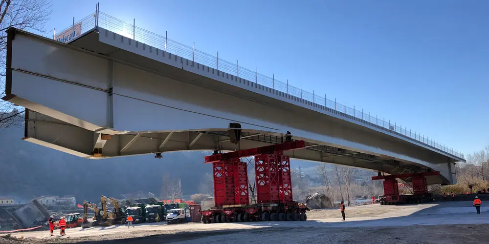
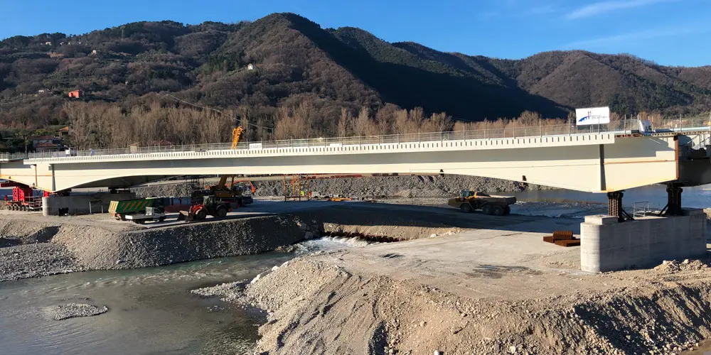
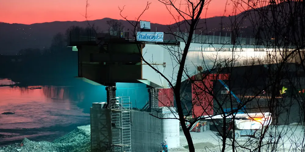
The bridge over the river Magra at Km 10 + 422, needed to be rebuilt after the collapse of the existing bridge. It is made with a girder deck in a mixed steel-concrete system and with a static scheme of continuous beam on 4 spans 57.00 + 2 x 90.00 + 54.00 m, for a total length of 291 m.

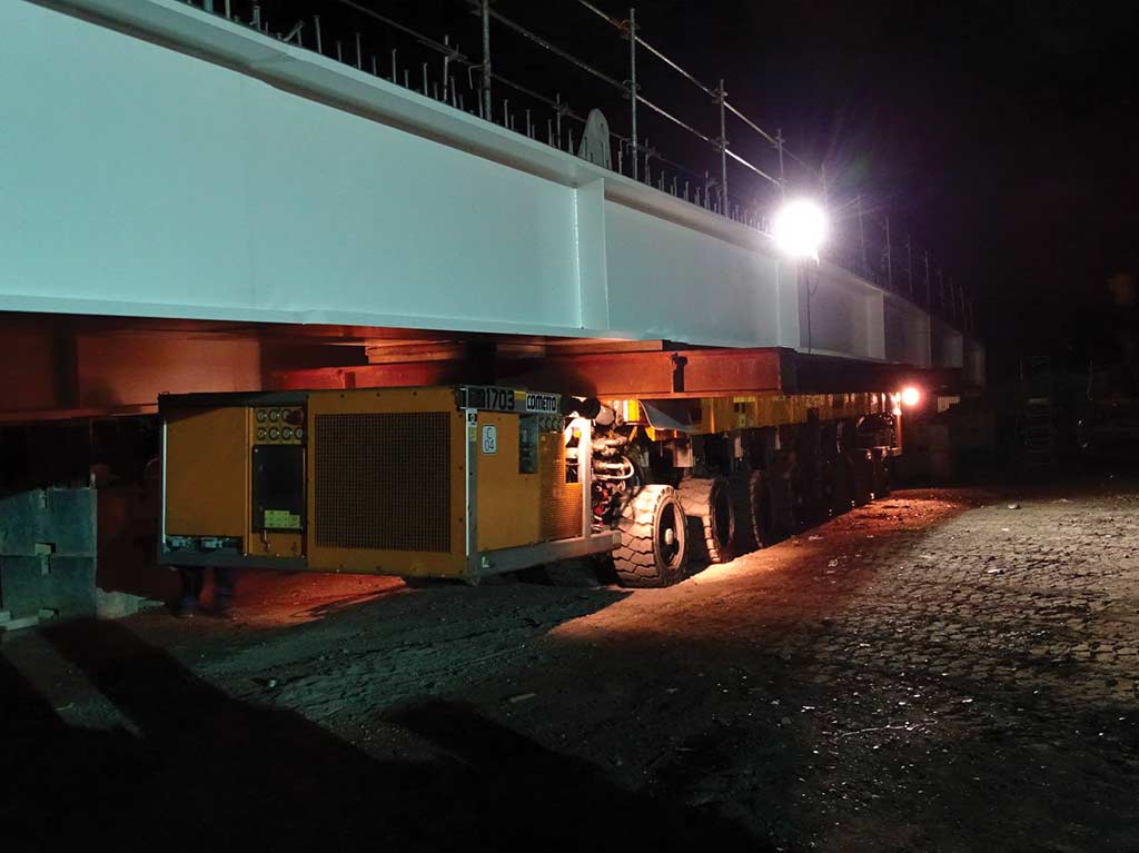
The steel structure was divided into four macro-segments, entirely assembled at the construction site on the river bank by welding the elementary segments. Each of them was then hoisted up on provisional support and transported to their final location by SPTM, after being positioned at height on provisional supports that were also transported.
The assembly project consisted in checking the girders in each phase and in studying of the various proceedings needed to align the four segments before execution of welded joints.

Ponte sul fiume Magra

The steel structure was divided into four macro-segments, entirely assembled at the construction site on the river bank by welding the elementary segments. Each of them was then hoisted up on provisional support and transported to their final location by SPTM, after being positioned at height on provisional supports that were also transported.
The assembly project consisted in checking the girders in each phase and in studying of the various proceedings needed to align the four segments before execution of welded joints.

Arch bridge in Moggio Udinese

Erection design.

Category: Erections
Services: Final Design
Period: June 2020 – August 2020
Client: BIT s.p.a.

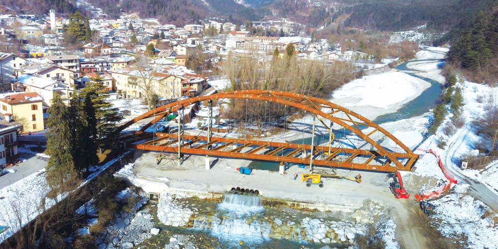
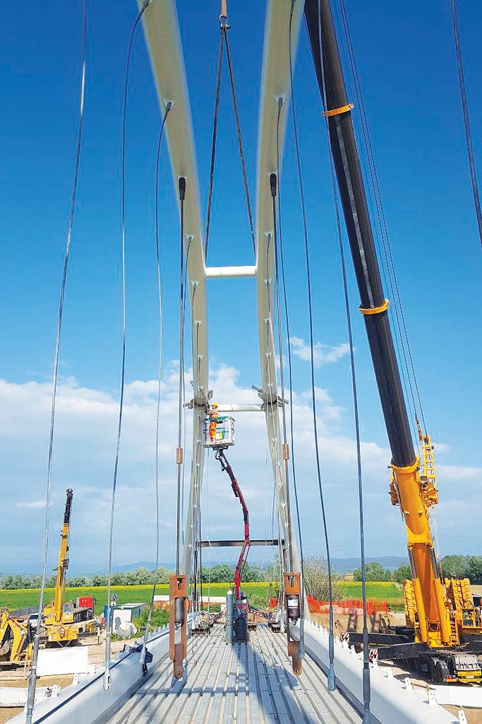
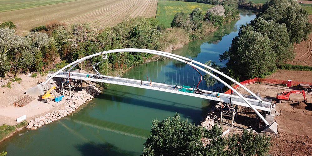
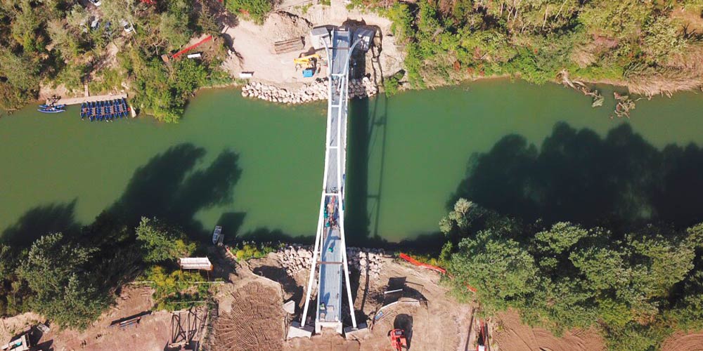
The work concerns the assembly plan of a bridge located in Moggio Udinese, which has a double parallel circular arch structure with calculation span in the axis of supports equal to 74.96m, total length equal to 77.1m, overall width of the roadway. equal to 9.40m, arrow of the arches 14m approx .. The bridge is characterized by a deck which is hung from the arches by means of bar hangers. The deck is made of longitudinal tubular beams and double T crosspieces to support a reinforced concrete slab. The two arches with tubular section are spaced in plan by about 4.6m due to the oblique supports.
First, the lateral segments of the deck beams were mounted, supported by temporary piers placed in the riverbed at the thirds of the span (near the deck joint).

The segment is then erected in the key of the deck and the relative crosspieces. We then proceed with the assembly of the two lateral arch segments supported by a temporary column that stands out from the provisional pile. To close the static scheme, the central segment of arch is then erected. Arch and deck are supported in the provisional phases by saddles suitably shaped and sliding in the longitudinal direction to allow the necessary geometric adjustments.

Bridge over the Ombrone River

Erection design of a cycle-pedestrian on the river Ombrone.

Category: Erections
Services: Final Design
Period: June 2014 – October 2014
Client: Bit S.p.a.
Amount: 1.399.601,87 € (Categories IXb, IXc, VIa)

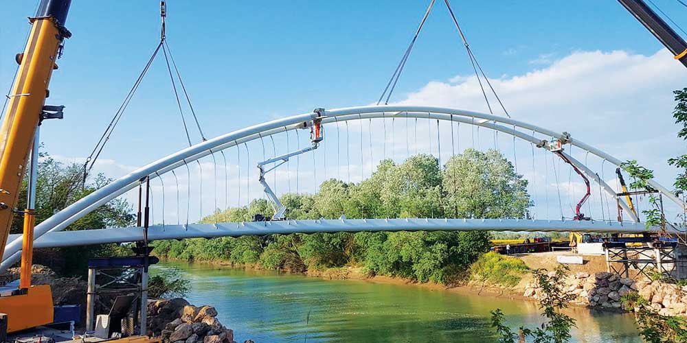
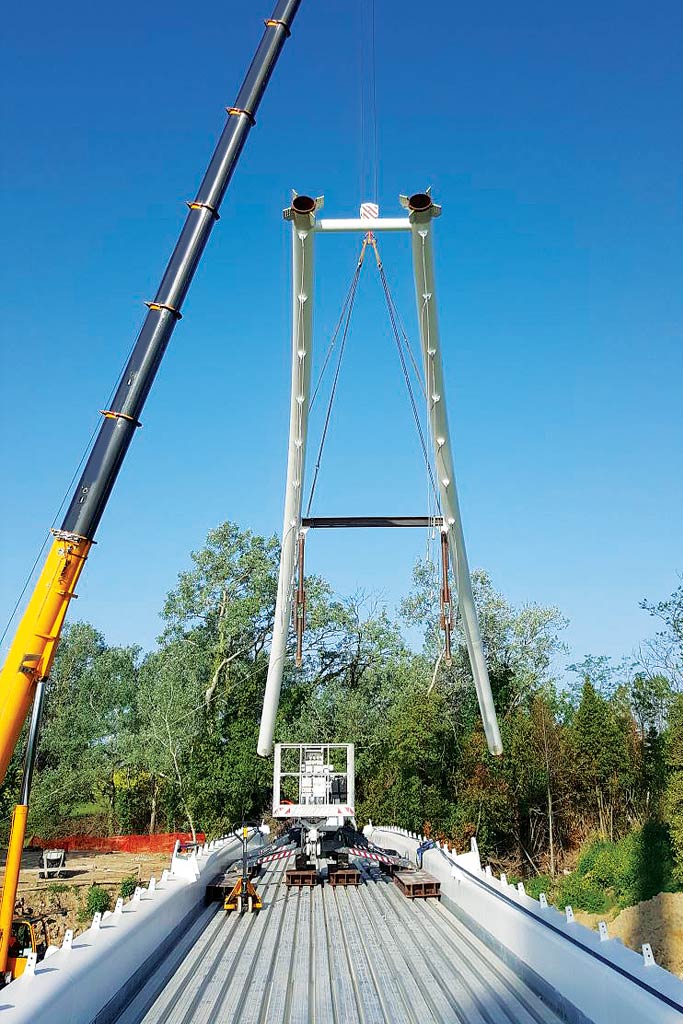
The final design of a steel arched cycle-pedestrian walkway. The deck is made with two lateral beams, supported by the tubular arches by means of a suspension system, with hangers converging towards the center.

The final design of a steel arched cycle-pedestrian walkway. The deck is made with two lateral beams, supported by the tubular arches by means of a suspension system, with hangers converging towards the center.

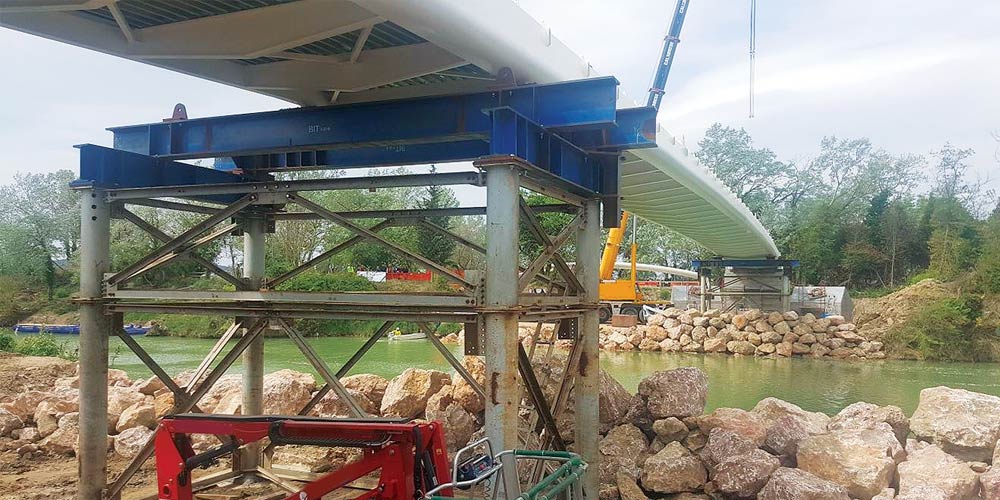
The main deck beams, made with a C-shaped cross section composed of bent metal sheets by welding, are connected with metal crosspieces in a double T section of variable height, tapered at the connection to the chain beam and arranged at the pitch of the hangers, i.e. every 2 m.

The main deck beams, made with a C-shaped cross section composed of bent metal sheets by welding, are connected with metal crosspieces in a double T section of variable height, tapered at the connection to the chain beam and arranged at the pitch of the hangers, i.e. every 2 m.

The hangers are made with full locked coil ropes with a theoretical diameter of 20 mm connected to the deck with an adjustable fork terminal and to the arch with a fixed fork terminal.

The hangers are made with full locked coil ropes with a theoretical diameter of 20 mm connected to the deck with an adjustable fork terminal and to the arch with a fixed fork terminal.

The decking is made with a 12 cm thick corrugated sheet slab resisting in the longitudinal direction between two transverse beams.

The decking is made with a 12 cm thick corrugated sheet slab resisting in the longitudinal direction between two transverse beams.

The main geometric features of the work are:
• Walkway span approx.72 m
• Height of the arches about 15.00 m
• Effective deck width m 3.50

The main geometric features of the work are:
• Walkway span approx.72 m
• Height of the arches about 15.00 m
• Effective deck width m 3.50

Bonneville Viaduct Mont Blanc Motorway

Erection design.

Category: Erections
Services: Final Design
Period: October 2018– November 2019
Client: BIT spa – Mont Blanc Motorway and Tunnel Company

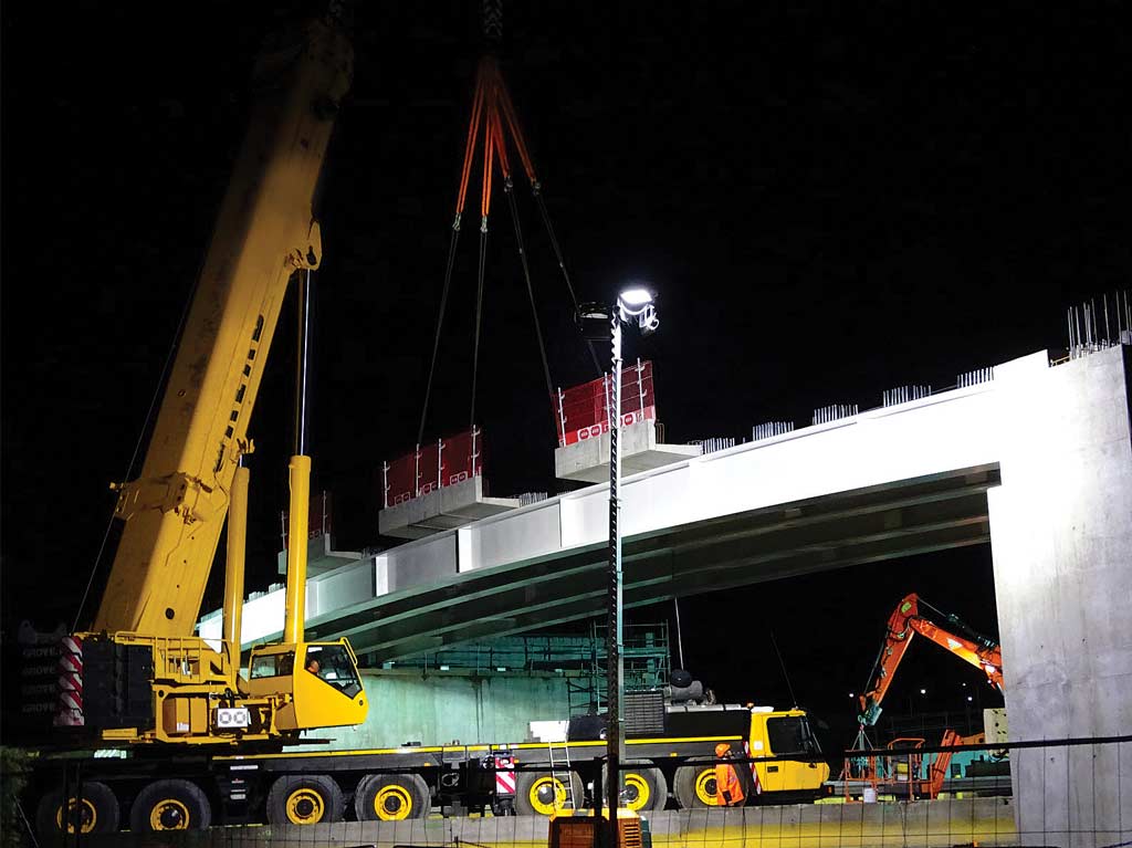
The deck was divided into coupled beams (BiPoutres), pre-assembled in the workshop, which were then transported to an area close to the final site, assembled and placed in geometry on temporary supports. By means of trolleys, the BiPoutres were moved to the foot of the work, to then be lifted and positioned in their final configuration by cranes. Particular attention was paid to checking the stability during the lifting, laying and casting of the deck.

The deck was divided into coupled beams (BiPoutres), pre-assembled in the workshop, which were then transported to an area close to the final site, assembled and placed in geometry on temporary supports. By means of trolleys, the BiPoutres were moved to the foot of the work, to then be lifted and positioned in their final configuration by cranes. Particular attention was paid to checking the stability during the lifting, laying and casting of the deck.

To ensure the rotations of the deck during the casting phase, it was necessary to provide provisional supports to be replaced when the casting is hardened with the definitive supports. Interference with the highway has been reduced to a minimum: the assembly operations were completed in just two nighttime interruptions granted by the highway manager.

To ensure the rotations of the deck during the casting phase, it was necessary to provide provisional supports to be replaced when the casting is hardened with the definitive supports. Interference with the highway has been reduced to a minimum: the assembly operations were completed in just two nighttime interruptions granted by the highway manager.

Cité Musicale

Assembly of the metal structures for the roof of the auditorium

Category: Erections
Services: Final Design
Period: January 2015 – July 2015
Client: Cordioli S.p.a. Bouygues Batiment
Value: approximately €1,200,000.00 ( Category IXb )

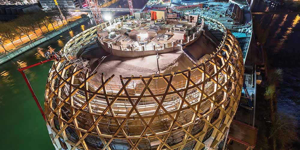
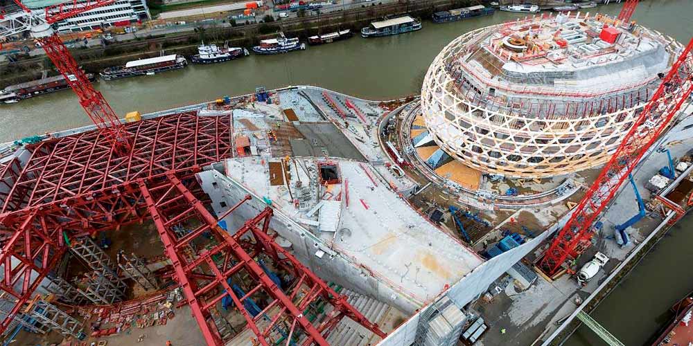
Final design of the assembly of the metal structures of the auditorium roof, including the study of the effects of the assembly sequence on the assembly structures and the study of the assembly equipment with particular attention to the temporary piers to be used to support the trussed beams, the transverse temporary retainers and longitudinal elements and the elements for distributing the loads at the base of the temporary towers.

Final design of the assembly of the metal structures of the auditorium roof, including the study of the effects of the assembly sequence on the assembly structures and the study of the assembly equipment with particular attention to the temporary piers to be used to support the trussed beams, the transverse temporary retainers and longitudinal elements and the elements for distributing the loads at the base of the temporary towers.

Study of the storage and assembly and lifting sequence of elementary segments of lattice beams.

Study of the storage and assembly and lifting sequence of elementary segments of lattice beams.

Bologna exhibitions – New Pavilion 37

Erection design of the fixed and moving part of the cover.

Category: Erections
Services: Final Design
Period: November 2019 – May 2020
Client: Cimolai s.p.a.

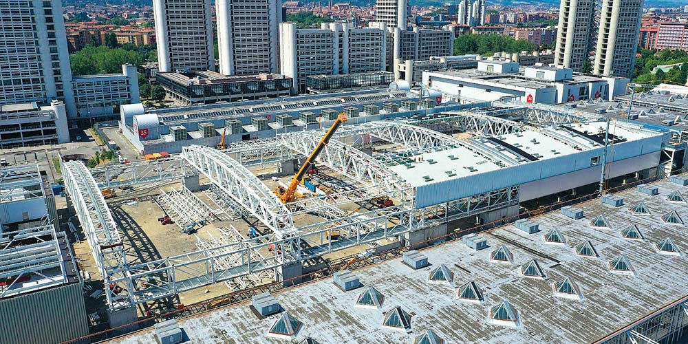
The roof of Pavilion 37 has plan dimensions of 80.8 m x 184 m and height of 23m and is entirely made with spatial lattices in metal carpentry.

The roof of Pavilion 37 has plan dimensions of 80.8 m x 184 m and height of 23m and is entirely made with spatial lattices in metal carpentry.

The fixed roof is made up transversely of main trusses, trusses with variable height from 2.8 m to 7 m span 72.8 m at a center distance of 36 m, by longitudinal secondary trusses.

The fixed roof is made up transversely of main trusses, trusses with variable height from 2.8 m to 7 m span 72.8 m at a center distance of 36 m, by longitudinal secondary trusses.

The mobile roof covers the central portion and consists of two spatial trussed structures with plan dimensions of 18×180 m which slide on the fixed roof by means of roller conveyors resting on runways fixed on the main trusses. First, the main trusses were assembled near the final site and raised by tandem lift, and then the secondary trusses.

The mobile roof covers the central portion and consists of two spatial trussed structures with plan dimensions of 18×180 m which slide on the fixed roof by means of roller conveyors resting on runways fixed on the main trusses. First, the main trusses were assembled near the final site and raised by tandem lift, and then the secondary trusses.

Once the fixed cover was completed, the semi-mobile cover, divided into 5 segments, was lifted by crane and moved to its final position by means of a strand jack using final rollers and rails. To restore the congruence of the mobile cover, appropriate constraints were applied by means of jacks on supporting alignments.

Once the fixed cover was completed, the semi-mobile cover, divided into 5 segments, was lifted by crane and moved to its final position by means of a strand jack using final rollers and rails. To restore the congruence of the mobile cover, appropriate constraints were applied by means of jacks on supporting alignments.